Sign In
Upload
Manuals
Brands
Garmin Manuals
GPS
GNC 255
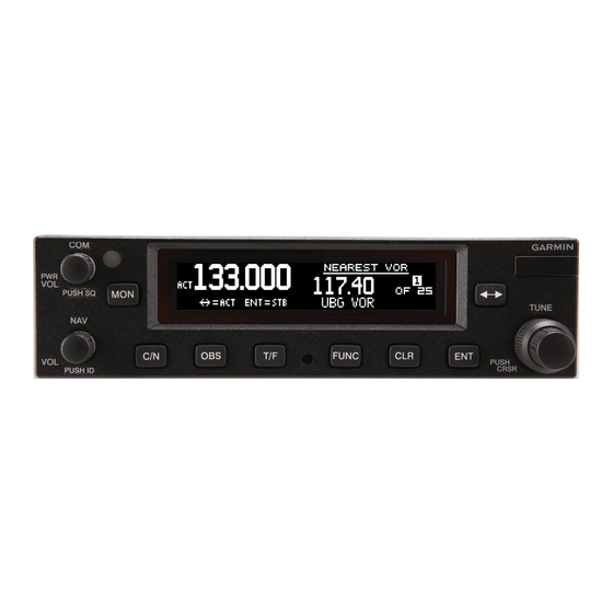
User Manuals: Garmin GNC 255 Communication Radio
Manuals and User Guides for Garmin GNC 255 Communication Radio. We have
3
Garmin GNC 255 Communication Radio manuals available for free PDF download: Installation Manual, Pilot's Manual
Garmin GNC 255 Installation Manual (138 pages)
TSO Installation Manual
Brand:
Garmin
| Category:
Transceiver
| Size: 7 MB
Table of Contents
Table of Contents
7
1 General Description
15
Introduction
15
Equipment Description
15
Table 1-1. TSO-Certified Units
15
Technical Specifications
16
Physical Characteristics
16
General Specifications
16
Display
17
COM Specifications
17
VOR Specifications
18
LOC Specifications
19
Glideslope Specifications
20
Table 1-2. GTR/GNC Current Specifications
21
License Requirements
22
Regulatory Compliance
23
Non-TSO Functions
23
Table 1-3. TSO Authorization and Advisory Circular References
23
Table 1-4. System Functions
23
TSO Deviations
24
FCC Grant of Equipment Authorization
24
GTR/GNC Database
25
Aviation Limited Warranty
25
2 Limitations
27
Installation
27
Aircraft Radio
27
3 Installation Overview
29
Introduction
29
Antenna Considerations
29
COM Antenna Location
29
Interference of GPS
30
GTR/GNC Mounting Considerations
30
Cabling and Wiring Considerations
31
Air Circulation and Cooling
32
Compass Safe Distance
32
4 Installation Procedures
33
Unit and Accessories
33
Miscellaneous Options
33
Table 4-1. Catalog Part Numbers
33
Table 4-2. Standard Kit Accessories
33
Optional Reference Material
34
Installation Materials Required but Not Supplied
34
Accessories Required but Not Supplied
34
Materials Required but Not Supplied (New Installations Only)
34
Special Tools Required
35
Table 4-3. Recommended Crimp Tools (or Equivalent)
35
Coaxial Cable Installation
36
Figure 4-1. Coaxial Cable Installation
36
Equipment Mounting
37
Rack Installation
37
Table 4-4. Socket Contact Part Numbers
37
GTR/GNC Unit Insertion and Removal
38
Unit Replacement
38
Antenna Installation and Connections
38
COM Antenna
38
5 Connector Pinout Information
39
Pin Function List
39
P2001 Connector - COM Board
39
P2002 Connector - NAV Board
41
Power, Lighting, and Antennas
43
Power
43
Lighting Bus
44
Antennas
44
Serial Data - RS-232
44
COM Discrete Inputs
47
VOR/ILS Audio
48
VOR/ILS Discrete Inputs
48
VOR/ILS Indicator
49
Rmi/Obi
51
DME Tuning
52
6 Post Installation Configuration and Checkout Procedures
55
System Configuration Overview
55
Mounting, Wiring, and Power Checks
55
Connector Engagement Check
56
Configuration Mode Operations
56
Figure 6-1. Configuration Mode Home Page
56
SYS Configuration
57
Figure 6-2. Serial Port Page
57
Figure 6-3. DST Display Page
57
Table 6-1. Serial Port Selections
57
Figure 6-4. Intercom Enable Page
58
Figure 6-5. Backlight Page
58
Table 6-2. Intercom Enable Page Selections
58
Table 6-3. Backlight Selections
58
Table 6-4. Photocell Page Parameter Description
59
Figure 6-7. Lighting Bus Page
60
Figure 6-8. Display Information Pages
60
Table 6-5. Lighting Bus Parameter Description
60
NAV Configuration (GNC Only)
61
Figure 6-9. Display Update Page
61
Figure 6-10. CDI Indicator Page
61
Table 6-6. CDI Indicator Selections
61
Figure 6-11. ARINC 429 Page
62
Table 6-7. ARINC 429 Configuration Speed (TX)
62
Table 6-8. SDI Selections
62
Table 6-9. DME Settings
62
COM Configuration
63
Figure 6-12. NAV Information Page
63
Figure 6-13. NAV Software Update Page
63
Figure 6-14. MIC Gain Page
63
Table 6-10. A429 Settings
63
Figure 6-15. COM RX Squelch Page
64
Figure 6-16. COM Information Page
64
Figure 6-17. COM Software Update Page
64
Audio Configuration
65
Figure 6-18. COM Sidetone Page
65
Figure 6-19. MIX NAV Audio Page
65
Figure 6-20. Hi-Fidelity Audio Page
65
Log Functions
66
Figure 6-21. Download Log Page
66
Figure 6-22. Clear Error Logs Page
66
Ground Checks (Configuration Mode)
67
Calibrate Resolver (GNC Only)
67
Figure 6-23. Calibrate OBS Resolver Page
67
Flags Check (GNC Only)
68
Vor/Localizer/Glideslope Indicator (GNC Only)
68
Figure 6-24. Test Analog Flags Page
68
Figure 6-25. Test CDI/VDI Page
68
Lighting Bus Interface Check
69
Ground Checks (Normal Mode)
70
Discrete Input Checkout
70
VHF NAV Checkout
70
NAV Audio Check (Audio Panel Installations) (GNC Only)
70
Table 6-11. Discrete Input Pins
70
Vhf Com
71
Interface Checkout
72
Flight Checks
73
COM Flight Check
73
VOR Flight Check (GNC Only)
73
ILS Flight Check (GNC Only)
73
Software Loading
74
Creating a GTR/GNC Software Loader USB Flash Drive
74
Loading Software to the GTR/GNC
75
Figure 6-26. USB Update Progress
75
Load Database
76
Documentation Checks
76
Airplane Flight Manual Supplement
76
Figure 6-27. Database Update Display
76
Figure 6-28. Verify Database Version
76
7 Periodic Maintenance
77
Equipment Calibration
77
VOR Checks
77
Cleaning
77
Appendix Aenvironmental Qualification Form
79
Appendix Bgtr/Gnc Data Format
81
Aviation Data Format
81
Table B-1. Aviation Output Sentence Format
82
Table B-2. Type 2 Aviation Output Sentence Format
84
NMEA Data Format
85
Table B-3. Input Message Summary
99
Table B-4. Output Message Summary
99
Appendix Cmechanical Drawings
101
Drawing List
101
Figure C-1. GTR/GNC Dimensions
101
Figure C-2. GTR/GNC Mounting Rack
101
Figure C-3. GNC Center of Gravity
101
Figure C-4. GTR Center of Gravity
101
Figure C-5. GTR/GNC Rear Connector Layout Detail
101
Figure C-6. Panel Cutout Detail
101
Figure C-7. GTR Mounting Rack
101
Appendix Dinterconnect Diagrams
111
Drawing List
111
Figure D-1. GTR/GNC System Interface Diagram
111
Figure D-2. GTR/GNC Typical Installation
114
Figure D-3. GTR/GNC Power Lighting Configuration Interconnect
116
Figure D-4. GTR/GNC - Antennas Interconnect
117
Figure D-5. GTR/GNC - Audio Panel Interconnect
121
Figure D-6. GTR/GNC - MIC Interconnect
123
Figure D-7. GTR/GNC - VOR/ILS Interconnect
124
Figure D-8. GTR/GNC Switches Interconnect
126
Figure D-9. RMI OBI Interconnect
127
Figure D-10. GNC - King Serial DME - Remote Mount Interconnect
128
Figure D-11. Parallel 2 of 5 DME Tuning Interconnect
130
Figure D-12. Parallel Slip Code DME Tuning Interconnect
132
Advertisement
Garmin GNC 255 Installation Manual (132 pages)
TSO
Brand:
Garmin
| Category:
GPS
| Size: 7 MB
Table of Contents
Table of Contents
6
1 General Description
12
Introduction
12
Equipment Description
12
Table 1-1 TSO-Certified Units
12
General Specifications
14
Table 1-2 Physical Specifications
14
Table 1-3 Display Specifications
14
COM Specifications
15
Table 1-4 COM Transmitter Specifications
15
Table 1-5 COM Receiver Specifications
16
VOR Specifications
17
Table 1-6 vor Specifications
17
LOC Specifications
18
Table 1-7 LOC Specifications
18
Glideslope Specifications
19
Table 1-8 Glideslope Specifications
19
Current Draw Specifications
20
Table 1-9 GTR/GNC Current Draw Specifications
20
License Requirements
21
Certification
22
Table 1-10 TSO Authorization and Advisory Circular References
22
Table 1-11 System Functions
22
GTR/GNC Database
24
Aviation Limited Warranty
25
2 Limitations
26
Installation
26
Aircraft Radio
26
3 Installation Overview
27
Introduction
27
Antenna Considerations
27
GTR/GNC Mounting Considerations
28
Cabling and Wiring Considerations
29
Air Circulation and Cooling
29
Compass Safe Distance
29
4 Installation Procedures
30
Unit and Accessories
30
Miscellaneous Options
30
Table 4-1 Catalog P/Ns
30
Table 4-2 Standard Kit Accessories
30
Table 4-3 Miscellaneous Options
30
Optional Reference Material
31
Installation Materials Required but Not Supplied
31
Table 4-4 Optional Reference Material
31
Special Tools Required
32
Table 4-5 Recommended Crimp Tools (or Equivalent)
32
Table 4-6 Socket Contact P/Ns
32
Coaxial Cable Installation
33
Equipment Mounting
33
COM Antenna Installation and Connections
34
5 Connector Pinout Information
35
Pin Function List
35
Power, Lighting, and Antennas
39
6 Post Installation Configuration and Checkout Procedures
50
System Configuration Overview
50
Mounting, Wiring, and Power Checks
50
Connector Engagement Check
51
Configuration Mode Operations
51
Figure 6-1 Configuration Mode Page
51
Figure 6-2 Serial Port Page
52
Figure 6-3 DST Priority Page
52
Table 6-1 Serial Port Selections
52
Figure 6-4 Intercom Enable Page
53
Figure 6-5 Backlight Page
53
Table 6-2 Intercom Enable Page Selections
53
Table 6-3 Backlight Selections
53
Table 6-4 Photocell Page Parameter Description
54
Figure 6-7 Lighting Bus Page
55
Figure 6-8 Display Information Pages
55
Table 6-5 Lighting Bus Parameter Description
55
Figure 6-9 Software Update Page
56
Figure 6-10 CDI Indicator Page
56
Table 6-6 CDI Indicator Selections
56
Figure 6-11 Calibrate OBS Resolver Page
57
Figure 6-12 ARINC 429 Page
57
Table 6-7 ARINC 429 Configuration Speed (TX)
57
Table 6-8 SDI Selections
57
Table 6-9 DME Settings
58
Table 6-10 A429 Settings
58
Figure 6-13 NAV Information Page
59
Figure 6-14 NAV Software Update Page
59
Figure 6-15 MIC Gain Page
60
Figure 6-16 COM RX Squelch Page
60
Figure 6-17 COM Information Page
61
Table 6-11 COM RX Squelch Selections
61
Table 6-12 COM RX Squelch Settings
61
Figure 6-18 COM Software Update Page
62
Figure 6-19 COM Sidetone Page
62
Table 6-13 COM Sidetone Mode Selections
62
Figure 6-20 MIX NAV Audio Page
63
Figure 6-21 Hi-Fidelity Audio Page
63
Table 6-14 COM Sidetone Pilot Control
63
Figure 6-22 Download Log Page
64
Figure 6-23 Clear Error Logs Page
64
Ground Checks (Configuration Mode)
65
Figure 6-24 Calibrate OBS Resolver Page
65
Figure 6-25 Test Analog Flags Page
66
Figure 6-26 Test CDI/VDI Page
67
Ground Checks (Normal Mode)
68
Table 6-15 Discrete Input Pins
68
Flight Checks
71
Software Loading
72
Table 6-16 Software Compatibility
72
Figure 6-27 USB Update Progress
73
Figure 6-28 Database Update Page
74
Figure 6-29 Database Info Page
74
7 Continued Airworthiness
75
Appendix A Environmental Qualification Form
76
Appendix B Gtr/Gnc Data Format
77
Aviation Format
77
Table B-1 Aviation Output Sentence Format
78
Table B-2 Type 2 Aviation Output Sentence Format
80
NMEA Data Format
81
Table B-3 Input Message Summary
97
Table B-4 Output Message Summary
97
Appendix Cmechanical Drawings
98
Drawing List
98
Figure C-1 GTR/GNC Dimensions
98
Figure C-2 GTR/GNC Mounting Rack
98
Figure C-3 GNC Center of Gravity
98
Figure C-4 GTR Center of Gravity
98
Figure C-5 GTR/GNC Rear Connector Layout Detail
98
Figure C-6 Panel Cutout Detail
98
Figure C-7 GTR Mounting Rack
98
Appendix D Interconnect Diagrams
106
Drawing List
106
Figure D-1 GTR/GNC System Interface Diagram
106
Figure D-3 GTR/GNC Power Lighting Configuration Interconnect
106
Figure D-6 GTR/GNC - MIC Interconnect
106
Figure D-8 GTR/GNC Switches Interconnect
106
Figure D-9 GNC - RMI OBI Interconnect
106
Figure D-2 GTR/GNC Typical Installation
108
Figure D-4 GTR/GNC - Antennas Interconnect
111
Figure D-5 GTR/GNC - Audio Panel Interconnect
115
Figure D-7 GNC - VOR/ILS Interconnect
119
Figure D-10 GNC - King Serial DME - Remote Mount Interconnect
123
Figure D-11 GNC - Parallel 2 of 5 DME Tuning Interconnect
125
Figure D-12 GNC - Parallel Slip Code DME Tuning Interconnect
126
Figure D-13 GNC - King Serial DME - Panel Mount Interconnect
128
Figure D-14 GNC - GDU 620 Interconnect
129
Figure D-15 GTR/GNC - GTN 6XX/7XX, GNS 400W/500W, and GNS 480 Interconnect
130
Figure D-16 GTR/GNC - GMX 200 Interconnect
131
Garmin GNC 255 Pilot's Manual (64 pages)
GNC255A/255B Pilot's Guide
Brand:
Garmin
| Category:
GPS
| Size: 1 MB
Table of Contents
Limited Warranty
3
Product Registration and Support
7
Table of Contents
9
1 Getting Started
13
Product Description
13
Pilot Controls
14
Power/Com Volume/Squelch Knob
14
Nav Volume/ID Knob
14
Tuning LARGE/SMALL Concentric (Cursor) Knobs
15
FLIP/FLOP Key
15
C/N (Com/Nav) Key
15
OBS Key
15
T/F (To/From) Key
15
CLR (Clear) Key
15
ENT (Enter) Key
15
FUNC (Function) Key
16
MON (Monitor) Key
16
USB Port
16
2 Basic Operation
17
Power on
17
Com Radio
17
Selecting a Com Frequency
17
Monitoring the Standby Com Channel
18
Saving a Com Channel
18
Com Database Look-Up
20
Frequency Database Reverse Look-Up
20
Emergency Channel
21
Stuck MIC
21
Remote Frequency Selection Control
21
Nav Radio
22
Selecting a Nav Frequency
22
Saving a Nav Channel
22
Listening to the Nav Audio Channel
23
OBS Mode
24
Distance/Speed/Time (DST) Display
25
3 Functions
27
Functions Description
27
Com Frequencies
28
Recent Com Frequencies
28
Com User Frequencies
29
Viewing the Com User Frequency
29
Deleting the Com User Frequency
29
Editing a Com User Frequency
30
Com Database Frequencies
31
Com Nearest Airports (APT)
32
Com Nearest Area Control Center (ACC) Frequencies
33
Com Nearest Flight Service Station (FSS) Frequencies
34
Com Nearest Weather (WX) Frequencies
35
Nav Frequencies
36
Recent Nav Frequencies
36
Nav User Frequencies
37
Viewing the Nav User Frequency
37
Deleting the Nav User Frequency
37
Editing a Nav User Frequency
38
Nav Database Frequencies
39
Nav Nearest vor
40
ICS Configuration
41
Adjust Intercom
41
Aux Audio
42
Intercom On/Off
43
Speaker On/Off
43
System Configuration
44
Com Spacing
44
Display Brightness
45
Display Contrast
46
Database Info
46
Load Database
47
Software Version
48
Serial Number
48
Timers
49
Setting up the Count down Timer
49
Setting up the Count up Timer
50
Garmin GNC 255A/255B Pilot's Guide 190-01182-01 Rev. a
50
Viewing Timers in the Com Display
50
4 Appendix
53
Troubleshooting
53
Updating the Frequency Database
55
Downloading the Frequency Database
55
Updating the GNC 255 Frequency Database
55
Messages
56
Index
61
Advertisement
Advertisement
Related Products
Garmin GNC 250
Garmin GNC 250XL
Garmin GNC 215
Garmin GNC 300XL TSO
Garmin GNC 300TSO
Garmin GNC 300
Garmin GNC 420W
Garmin GNC 420AW
Garmin GNC 520
Garmin GNC 530W
Garmin Categories
GPS
Watch
Car Navigation system
Avionics Display
Marine Equipment
More Garmin Manuals
Login
Sign In
OR
Sign in with Facebook
Sign in with Google
Upload manual
Upload from disk
Upload from URL