Sign In
Upload
Manuals
Brands
Gardner Denver Manuals
Water Pump
9CDL R Series
Gardner Denver 9CDL R Series Manuals
Manuals and User Guides for Gardner Denver 9CDL R Series. We have
1
Gardner Denver 9CDL R Series manual available for free PDF download: Parts List Operating And Service Manual
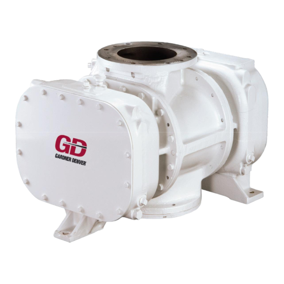
Gardner Denver 9CDL R Series Parts List Operating And Service Manual (52 pages)
BLOWERS / VACUUM PUMPS
Brand:
Gardner Denver
| Category:
Water Pump
| Size: 1 MB
Table of Contents
Maintain Blower Reliability and Performance
2
Foreword
3
Table of Contents
4
Index
5
List of Illustrations
6
Safety Precautions
7
Introduction Your Key to Trouble Free Service
8
Section 1 Equipment Check
8
Section 2 Installation
9
Figure 2-1 - Operating Principle
9
Figure 2-2 - Accessories and Safety Devices
10
Figure 2-3 - Belt Drive Overhung Load Calculations
13
Figure 2-4 - Outline Dimensions
16
Figure 2-5 - Outline Dimensions (Continued)
17
Section 3 Operation
18
Figure 3-1 - Maximum Rating
18
Figure 3-2 - Water Quality Requirements
19
Figure 3-3 - Liquid Rate
20
Figure 3-4- Inlet Water Injection Diagram
20
Figure 3-5 - Altitude - Pressure/Vacuum
21
Figure 3-6 - Minimum Speed, Maximum Pressure or Vacuum
22
Section 4 Maintenance
24
Figure 4-1 - Aeon Pd Synthetic Lubricant
24
Figure 4-2 - Synthetic Lubricant Chart
25
Figure 4-3 - Non-Synthetic Lubricant Chart
25
Figure 4-4 - Oil Bath Filter
27
Figure 4-5 - Oil Wetted Filter-Silencer
27
Figure 4-6 - Dry Type Filter and Filter-Silencer
28
Section 5 Parts List
30
Section 6 Disassembly Instructions
34
Figure 6-1 - Adaptor Plate
34
Figure 6-2 - Adaptor Plate
34
Figure 6-3- Spanner Wrench
34
Figure 6-4 - Adaptor Plates
34
Figure 6-5 - Puller
35
Figure 6-6 - Alternate Adaptor Plates
35
Figure 6-7 - Carrier Flange
36
Figure 6-8 - Bearing Clamp Plate Shim
36
Figure 6-9 - Puller
36
Section 7 Assembly Instructions
38
Figure 6-10 - Rotor Sling Removal
38
Figure 6-11 - Jack Screws
38
Figure 7-1 - Rotor Shaft Seals
39
Figure 7-2 - Bearing Spacers
39
Figure 7-3 - Discharge Opening
39
Figure 7-4 - Lower the Gate Rotor into the Housing Assembly
39
Figure 7-5 - Angular Contact Bearing Assembly
40
Figure 7-6 - Bearing Installation
40
Figure 7-7 - Discharge End Bearing Carrier
41
Figure 7-8 - Rotor End Clearnace Chart (Unit Cold)
41
Figure 7-9 - Depth Micrometer - Rotor Lobes
41
Figure 7-10 - Outside Micrometer - Thickness of Shims
41
Figure 7-11 - Discharge Opening & Dowel Pins
42
Figure 7-12 - Dial Indicator
42
Figure 7-13 - Seal Installation Guide
43
Figure 7-14 - Protective Installation Sleeves over each Shaft
43
Figure 7-15 - Micrometer - Thickness of Shaft Shim Set
44
Figure 7-16 - Shaft Extention
44
Figure 7-17 - Bearing Press Plates
45
Figure 7-18 - Bearing Clamp Plates
45
Figure 7-19 - Discharge Opening
45
Figure 7-20 - Reinforcing Plate
45
Figure 7-21 - End Cover Assembly
46
Figure 7-22 - Bearing Bore
47
Figure 7-23 - Depth Micrometer - Measure Distance to End of Bearing Spacer Assembly
47
Figure 7-24 - Oil Seal on Gate Rotor Shaft Assembly
47
Figure 7-25 - Slide Shims over the Shafts Assembly
47
Figure 7-26 - Press Plate and Jack Screw Assembly
48
Figure 7-27 - Install Hub & Pinion Pull Tight with Locking Device Assembly
48
Figure 7-28 - Mount Indicator and Button Bracket Assembly
48
Figure 7-29 - Smallest Minus Reading
49
Figure 7-30 - Smallest Plus Reading
49
Figure 7-31 - Setting the Interlobe Clearance
49
Figure 7-32 - Hold Gear & Shaft from Turning Tighten Five Gear to Hub "Nylok" Screws
49
Warranty
51
Advertisement
Advertisement
Related Products
Gardner Denver 9CDL13R
Gardner Denver 9CDL18R
Gardner Denver 9CDL23R
Gardner Denver 9VXRD1250
Gardner Denver 9VXRD1500
Gardner Denver 9VXRD3000
Gardner Denver 9VXRD1600
Gardner Denver 9VXRD2300
Gardner Denver 9VXRD025
Gardner Denver 9VXRD050
Gardner Denver Categories
Air Compressor
Water Pump
Dehumidifier
Controller
Compressor
More Gardner Denver Manuals
Login
Sign In
OR
Sign in with Facebook
Sign in with Google
Upload manual
Upload from disk
Upload from URL