Sign In
Upload
Manuals
Brands
Gamewell Manuals
Control Panel
GF505 Series
Gamewell GF505 Series Manuals
Manuals and User Guides for Gamewell GF505 Series. We have
1
Gamewell GF505 Series manual available for free PDF download: Installation, Programming, And Operation Manual
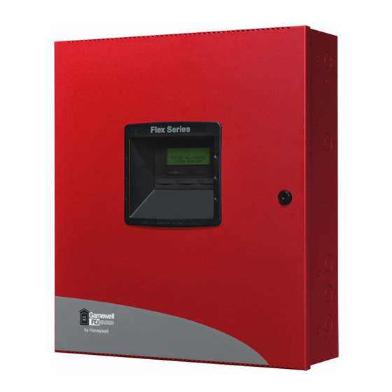
Gamewell GF505 Series Installation, Programming, And Operation Manual (144 pages)
Fire alarm control panels
Brand:
Gamewell
| Category:
Control Panel
| Size: 2 MB
Table of Contents
Fire Alarm System Limitations
2
Installation Precautions
3
Table of Contents
4
SECTION 1: Product Description
12
Product Features
12
Specifications
13
Controls and Indicators
15
Digital Alarm Communicator/Transmitter
17
Components
17
Optional Modules and Accessories
17
Telephone Requirements and Warnings
19
1: Telephone Circuitry
19
2: Digital Communicator
19
3: Telephone Company Rights and Warnings
20
SECTION 2: Installation
21
Backbox Mounting
21
Operating Power
24
Input Circuits
25
Output Circuits
27
1: Notification Appliance Circuits
27
2: Special Application DC Power Output Connections
28
3: Relays - Programmable
28
4: Remote Synchronization Output
29
Power-Limited Wiring Requirements
30
Digital Communicator
31
Installation of Optional Modules
32
1: CAC-5X Class a Converter Module
32
Installation
32
Wiring Nacs and Idcs for Class a
33
2: 4XTMF Option Module
34
4XTMF Transmitter Module Installation
35
ANN-BUS Devices
36
1: ANN-BUS Wiring
36
Calculating Wiring Distance for ANN-BUS Modules
36
Wiring Configuration
38
Powering ANN-BUS Devices from Auxiliary Power Supply
39
2: ANN-BUS Device Addressing
39
3: GFANN-80 Remote Fire Annunciator
40
4: Specifications
40
5: Installation
40
Mounting
40
Opening/Closing Annunciator
40
Wiring GFANN-80 to FACP
41
6: GFANN-S/PG Serial/Parallel Printer Interface Installation
43
PRN Printer Installation
43
Specifications
43
Connecting PRN Printer
44
Setting Printer Options
44
7: GFANN-I/O LED Driver Module
45
GFANN-I/O Board Layout
45
Specifications
45
GFANN-I/O Connection to FACP
46
GFANN-I/O Module LED Wiring
47
8: GFANN-LED Annunciator Module
48
GFANN-LED Board Layout
48
Mounting/Installation
48
Specifications
48
GFANN-LED Connection to FACP
49
9: GFANN-RLY Relay Module
50
GFANN-RLY Board Layout
50
Mounting/Installation
50
Specifications
50
GFANN-RLY Connection to FACP
51
SECTION 3: Programming
52
User Programming
52
Initial Power-Up
53
Programming Screens Description
53
Programming and Passwords
53
Master Programming Level
55
1=Input Zones
56
Zone Type
57
2: NAC (Notification Appliance Circuit)
63
Enabled
64
NAC Coding
64
Synchronized NAC Operation
65
Two Stage Operation
65
Silence
66
3=Relays
67
Auto Silence
67
Silence Inhibited
67
Relay Type
68
4: System Setup
69
PAS (Positive Alarm Sequence) Delay
70
Presignal Delay
70
Timers
70
AC Loss Delay
71
Waterflow Delay
71
Banner
72
Time
73
Time-Date
73
Clock Format
74
Date
74
Daylight Savings Time
74
5: Option Modules
75
Charger Disable
75
Trouble Reminder
75
Ann-Bus
76
ANN-BUS Enabled
76
BUS Modules
76
Auto-Configure
77
ANN-S/PG Options Screen
78
GFANN-I/O LED Zone Assignments
79
Options Screen
80
ANN-RLY Options Screen
81
Onboard DACT
82
Primary Phone
82
Central Station
83
Secondary Phone
83
Account Code
85
Test Time Interval
85
Hour Test Time
86
6: History
95
Erase History
95
View Events
95
7: Walktest
96
8: Clear Program
97
9: Password Change
97
Maintenance Programming Level
98
1: Input Zones - Enable/Disable
99
2=History
99
3=Walktest
100
4: Time-Date
101
SECTION 4: Operating Instructions
102
Panel Control Buttons
102
1: Acknowledge/Step
102
2: Alarm Silenced
102
3: Drill/Hold 2 Sec
102
4: Reset
102
LED Indicators
103
Normal Operation
103
Trouble Operation
104
Alarm Operation
105
Supervisory Operation
106
Process Monitor Operation
107
Hazard/Tornado Condition Operation
107
Medical Alert Condition Operation
107
Disable/Enable Operation
108
Waterflow Circuits Operation
108
Detector Functions
108
Time Functions: Real-Time Clock
108
Coded Operation
108
Presignal
109
Positive Alarm Sequence
109
Special System Timers
110
1: Silence Inhibit Timer
110
2: Autosilence Timer
110
3: Trouble Reminder
110
4: Waterflow Retard Timer
110
5: Alarm Verification (None or One Minute)
111
Walktest
111
Read Status
112
1=Input Zones
113
2: Nac
113
3=Relays
114
4: System Settings
114
5: Timers
115
6: Daylight Savings
115
7: History
116
8: Print
116
9: Ann-Bus
117
10: Central Station
118
11: Phone Line
118
SECTION 5: Central Station Communications
119
Transmittal Priorities
120
SECTION 6: Power Supply Calculations
122
Overview
122
Calculating the AC Branch Circuit
122
Calculating the System Current Draw
123
1: Overview
123
2: How to Use Table 6-3 on Page 124 to Calculate System Current Draw
123
Calculating the Battery Size
125
1: NFPA Battery Requirements
125
2: Selecting and Locating Batteries
125
APPENDIX A: Ademco Contact ID Format
126
Event Code Descriptions
126
A.1: Transmission Format between DACT and Receiver
126
A.2: Ademco Contact ID Typical Printout
126
APPENDIX Bnfpa Standard-Specific Requirements
131
Connection to FACP Dry Contacts
137
B.1: Central Station/Remote Station Transmitter Connection to FACP Dry Contacts
137
APPENDIX C: FACP with Keltron
138
Advertisement
Advertisement
Related Products
Gamewell GF510 Series
Gamewell Honeywell GWF-7075
Gamewell IdentiFlex 610
Gamewell ZNS
Gamewell Categories
Smoke Alarm
Control Panel
Fire Alarms
Gateway
Security System
More Gamewell Manuals
Login
Sign In
OR
Sign in with Facebook
Sign in with Google
Upload manual
Upload from disk
Upload from URL