Sign In
Upload
Manuals
Brands
Gamatronic Manuals
UPS
MEGA V2 250
Gamatronic MEGA V2 250 Manuals
Manuals and User Guides for Gamatronic MEGA V2 250. We have
1
Gamatronic MEGA V2 250 manual available for free PDF download: Installation Manual
Gamatronic MEGA V2 250 Installation Manual (66 pages)
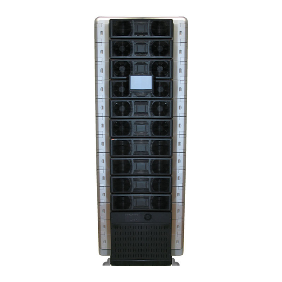
MODULAR UPS SYSTEM UP TO 250 KW
Brand:
Gamatronic
| Category:
UPS
| Size: 4.04 MB
Table of Contents
Table of Contents
3
Installation
9
Installation Checklist
9
Installation Procedure
11
Visual Inspection
11
Site Preparation - Physical
11
Figure 1: Recommended Clearances Around the Megav2 250 UPS
12
Table 1: Recommended Clearances
12
Site Preparation - Electrical
13
Cabling
13
Installing the Cable Guard
13
Figure 2: the Cable Guard (Without and with Its Rear Panel)
13
Figure 3: Attaching the Cable Guard
14
Neutral Line
15
Ac Input and Output Connections
15
Assembling and Connecting the Batteries
16
Table 2: Battery Lifetime Vs Environmental Temp. (Illustrative, as Per Eurobat)
16
Figure 4: Recommended Standard System Connections
17
Figure 5: Recommended System Connections, with Input Isolation Transformer
18
Table 3: Maximum Input Currents
19
Table 4: Recommended Circuit Breaker / Switch Ratings
19
Figure 6: Alternate Battery Connection Option
20
Connecting the Megav2 250 to the Electrical Panel
21
Figure 7: Power Terminals on the Rear of the Megav2 250
21
Emergency Power off - EPO (Manual)
22
EPO Indication for Battery Tripcoil
22
Figure 8: Connections for EPO Switch and EPO Indication
22
Input and Output Dry Contacts
23
Figure 9: Closer View of Dry Contact Terminals
23
Figure 10: Close-Up of Dry Contact Terminals
23
Powering-Up the System
24
Figure 11: Pin Usage in D9 Alarm Connector
24
Initial Configuration
25
Figure 12: Initial Configuration Wizard, "Welcome" Screen
25
Figure 13: Initial Config. Wizard: Password Entry
25
Figure 14: Initial Config. Wizard: Set Number of Modules
26
Figure 15: Initial Config. Wizard: Number of Battery Cabinets
27
Figure 16: Initial Config. Wizard: Set Battery Capacity
27
Figure 17: Initial Config. Wizard: Set Date and Time
28
Figure 18: Initial Config. Wizard: Set Time Zone
28
Figure 19: Finish Configuration Wizard
29
Continuing First-Time Start-Up Process
30
Figure 20: the "Alarms" Icon Indicates Alarm Conditions
30
Define the IP Address of Megav2 250
31
Figure 21: IP Address Configuration
31
Testing
32
Blackout Test
32
Test under Load
32
Check IP Communication with Controller
32
Figure 22: Network Connections Screen
33
Figure 23: Local Area Connection Properties Screen
33
Figure 24: Internet Protocol (TCP/IP) Properties Screen
34
Inserting and Removing Power Modules
35
Safety Considerations
35
Figure 25: Moving a Power Module Requires Two Persons
35
First-Time Insertion of Power Modules at System Installation
36
Figure 26: Left Side of a Module Viewed from the Front
36
Table 5: Key to Figure 26
36
Figure 27: Left Side of Module Shelves
37
Table 6: Key to Figure 27
37
Figure 28: Communication Cable on Right Side of Module
38
Replacement of a Module in an Installed System
39
Figure 29: Turning off a Module
39
Figure 30: "Status > Modules" Screen
39
Figure 31: Verifying Status of Replacement Module
41
Figure 32: Status > Modules > Output
41
Addition of a Module in an Installed System
43
Figure 33: Turning off a Module
43
Figure 34: Turning on a Module
44
Figure 35: Verifying Status of Added Module
44
Figure 36: Status > Modules > Output
45
Removing a Module from an Installed System
46
Figure 37: Turning off a Module
46
Figure 38: "Status > Modules" Screen
46
Installing the Lcd Screen
48
Figure 39: Opening the Cover of the LCD Mounting Point
48
Figure 40: the Mounting Post Is Revealed
48
Figure 41: Attaching the Clamp to the Mounting Post, Part 1
49
Figure 42: Attaching the Clamp to the Mounting Post, Part 2
49
Figure 43: Slide LCD Screen Onto the Mounting Clamp
50
Figure 44: the Screen's Cable Projects from Right Side of UPS Frame
51
Figure 45: Attach Comm. Cable to the LCD Screen
52
Replacing the Computer
53
Figure 46: the Megav2 250
53
Figure 47: the Front-Left of the Megav2 250
53
Figure 48: the Flat Cables
54
Figure 49: the Power Cord
54
Figure 50: the Left Side of the Computer
54
Figure 51: Two Screws on the Front of the Computer
55
Circuit Breaker Selectivity
56
Figure 52: a Ups's Bypass Circuit
56
Periodic Preventive Maintenance
58
Objectives
59
Recommended Tools
59
Maintenance Procedures and Report
60
Service and Repairs
63
Ega Specifications
64
Table 7: Technical Specifications
64
Advertisement
Advertisement
Related Products
Gamatronic MEGA V2 SA25
Gamatronic B60US-IB
Gamatronic Centric 100 kVA
Gamatronic CENTRIC 100 kW
Gamatronic Centric 120 kW
Gamatronic Centric 125 kVA
Gamatronic Centric 150 kVA
Gamatronic Centric 175 kVA
Gamatronic Centric 200 kVA
Gamatronic CENTRIC 200 kW
Gamatronic Categories
UPS
Measuring Instruments
Server
More Gamatronic Manuals
Login
Sign In
OR
Sign in with Facebook
Sign in with Google
Upload manual
Upload from disk
Upload from URL