Sign In
Upload
Manuals
Brands
G-U Manuals
Door Opening System
BKS SecureConnect 200
G-U BKS SecureConnect 200 Power Transfer Manuals
Manuals and User Guides for G-U BKS SecureConnect 200 Power Transfer. We have
1
G-U BKS SecureConnect 200 Power Transfer manual available for free PDF download: Mounting And Operation Instructions
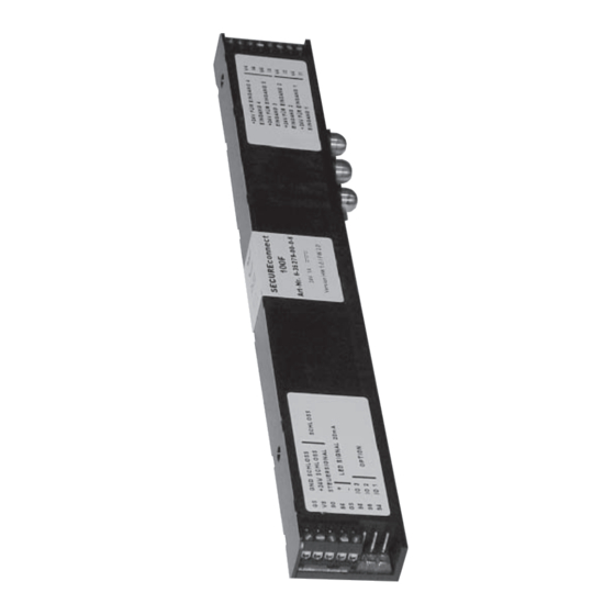
G-U BKS SecureConnect 200 Mounting And Operation Instructions (72 pages)
Power and data transmission unit
Brand:
G-U
| Category:
Door Opening System
| Size: 4 MB
Table of Contents
Deutsch
2
Table of Contents
2
1 Sicherheitshinweise
4
2 Information
4
Hinweise zur Anleitung
4
Packungsinhalt
5
3 Technische Beschreibung
6
Anwendungsbereich
6
Secureconnect 200R zum Einbau in den Türrahmen
6
Secureconnect 200F zum Einbau in den Türflügel
7
Technische Daten
7
Systemdarstellung
8
4 Sicherheitshinweise
9
5 Montagevorbereitung
10
Stulpblechmontage
10
Montage Kontaktträger und Kontaktplatte
11
Falzluft (Kammermaß) Einstellen
12
Vorbereitung zum Einbau in die Tür
13
6 Anschlusshinweise
14
Leitungsverlegung und Elektrischer Anschluss
14
Anschlüsse Secureconnect 200
14
Beschreibung der Anschlüsse SC 200F (Flügelteil)
14
Anschlussklemmen Rückmeldekontakte (I1 - I4 / V4)
14
Anschlussklemmen Elektrische Schlösser
15
Anschlussklemmen LED
15
Anschlussklemmen 94, 95, 96, GS (ZUKO-Modul)
15
Beschreibung der Anschlüsse SC 200R Rahmenteil
16
Externe DC 24 V Spannungsversorgung
16
Anschlussklemmen BKS-Net-BUS
16
Anschlussklemmen Steuereingänge
17
Anschluss AC 230 V Spannungsversorgung
17
7 Inbetriebnahme
18
Aufbau der Kommunikation
19
Pairing
19
Repairing
19
LED - Signalisierung
20
Anzeigen am Secureconnect 200R
20
Anzeigen am Secureconnect 200F
20
Funktionen mit Elektromotorischen Schlössern
21
Kurzzeit-Auf (Kurzzeitentriegelung)
21
Dauer-Auf (Entriegeln)
22
Tür Verriegeln
22
Funktionen mit EK-Schlössern
23
Tür Kurzzeit-Auf (Drücker Einkuppeln)
23
Tür Dauer-Auf
23
Tür Schließen (Drücker Auskuppeln)
23
Elektrische Funktionsprüfung
25
8 Anschlusszeichnungen
25
Fallenriegelüberwachung
25
Anschlussplan Secury Automatik mit A-Öffner
26
Ein- und Ausschalten des Tonsignals IM A-Öffner
27
Anschlussplan Motorschloss Serie 19
28
Anschlussplan EK-Schloss Serie 19
29
(Mit 14 Poligem Anschlusskabel)
30
Anschlussplan EK-Schloss Serie 21 (mit 8 Poligem Anschlusskabel)
31
Ansteuerung über IO-Module
32
Eingänge am IO-Modul
33
Ausgänge am IO-Modul
34
9 Inspektions- und Wartungsarbeiten
35
10 Entsorgung
35
English
36
1 Safety Instructions
38
2 Information
38
General Advice
38
Delivery Contents
39
3 Technical Description
40
Range of Application
40
Secureconnect 200R for Installation in the Door Frame Page
40
Secureconnect 200F for Installation in the Door Leaf Page
41
Technical Data
41
Schematic View
42
4 Safety Advice
43
5 Mounting Preparations
44
Mounting the Faceplates
44
Mounting the Contact Holder with Contact Plates
45
Regulating the Rebate Clearance
46
Installation in the Door
47
6 Wiring Advice
48
Wiring and Electrical Connection
48
Secureconnect 200 Terminals
48
Connection Terminals of Secureconnect 200F (Leaf Part)
48
Terminals for Monitoring Contacts (I1 - 14 / V4)
48
Connection Terminals for Electrical Locks
49
Connection Terminals for LED
49
Connection Terminals for Access Control Module
49
Connection Terminals of Secureconnect 200R (Frame Part)
50
Terminals for External DC 24 V Voltage Supply
50
Connection Terminals for BKS-NET Bus
50
Connection Terminals for Control Inputs
51
Connecting a AC 230 V Voltage Supply
51
7 Start-Up
52
Establishing Communication
53
Pairing
53
Re-Pairing
53
LED Signalling
54
LED Indication on Secureconnect 200R
54
LED Indication on Secureconnect 200F
54
Functions with Motor-Driven Locks
55
Short-Time OPEN (Short-Term Release)
55
Permanent OPEN (Unlocking)
56
Door Locking
56
Function with Electromechanical Locks ('EK')
57
Short-Time OPEN (Engaging the Lever Handle)
57
Permanent OPEN (Unlocking)
57
Door Closing (Disengaging the Lever Handle)
57
Electrical Function Test
59
8 Connection Diagrams
59
Latchbolt Monitoring
59
Switching the A-Opener's Acoustic Signal on and off
61
Connection Diagram of Motor-Driven Lock Series 19
62
Connection Diagram of 'EK' Lock Series 19
63
Connection Diagram of 'EK' Lock Series 21
64
(With 14-Wire Connecting Cable)
64
Connection Diagram of 'EK' Lock Series 21 (with 8-Wire Connecting Cable)
65
Control Via IO Modules
66
IO Module Inputs
67
IO Module Outputs
68
9 Inspection and Maintenance
69
10 Disposal
69
Advertisement
Advertisement
Related Products
G-U Secury 21 EK
G-U Secury 21 S
G-U Secury 21
G-U PRIME OFFICE 2170
G-U BKS B-744 Series
G-U BKS B-7441 Series
G-U OTS 733
G-U OTS 733 BG
G-U OTS 735
G-U OTS 735 BG
G-U Categories
DC Drives
Locks
Door Opening System
Door locks
Intercom System
More G-U Manuals
Login
Sign In
OR
Sign in with Facebook
Sign in with Google
Upload manual
Upload from disk
Upload from URL