Sign In
Upload
Manuals
Brands
Futurecom Manuals
Car Receiver
VRX1000
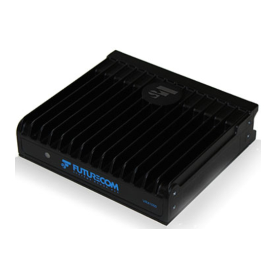
Futurecom VRX1000 Manuals
Manuals and User Guides for Futurecom VRX1000. We have
9
Futurecom VRX1000 manuals available for free PDF download: Installation And Programming Manual, Installation & Programming Manual, User Manual, Functional Description, Installation Manual
Futurecom VRX1000 Installation And Programming Manual (175 pages)
Brand:
Futurecom
| Category:
Car Receiver
| Size: 3 MB
Table of Contents
Table of Contents
12
Part I
17
Notations Used in this Manual
18
Declaration of Conformity
19
RF Energy Exposure Compliance, Awareness and Control Information and Operational Instructions
20
List of Tables
21
RF Exposure Label
21
FCC Label
21
Table 1 Minimum Lateral Distance from Antenna - VRX1000
21
Installation Requirements for Compliance with Radio Frequency (RF) Energy Exposure Safety Standards
22
Introduction
23
Table 2 VRX1000 Vs Infrastructure Compatibility (Voice and Signaling)
23
List of Figures
24
Identifying Your VRX1000 Model
24
Frequency Band of Operation
24
Cross-Band
24
Figure 1 Cross-Band VRX1000 - Conceptual Diagram
24
Figure 2 Cross-Band VRX1000 - Dimensions MM / [In]
25
In-Band
26
Figure 3 In-Band VRX1000 - Conceptual Diagram
26
Figure 4 In-Band VRX1000 - Flat Mount Dimensions MM / [In]
27
In-Band VRX1000 Dimensions
27
VRX1000 Installation Basics
28
Planning the Installation
28
Installation Tools Required
28
Figure 5 Cross-Band VRX1000 Mounting Details
29
In-Band VRX1000 Mounting
30
Figure 6 In-Band VRX1000 - Flat Mount Details
30
Figure 7 In-Band VRX1000 Stacked Mount Details
30
Mounting the Mobile Radio
31
Connecting the VRX1000 Cables
32
Figure 8 VRX1000 Connectors
32
Power Cable
33
RF Cables
34
Control Cables
34
Table 3 VRX1000 RF Cables
34
Table 4 VRX1000 Control Cable Types
34
Figure 9 VRX1000 Standard Control Cable (PN 7W087X07)
35
Figure 10 VRX1000 Y-Control Cable with AUX Extension (PN 7W087X08)
35
Figure 11 MSU Side DB25 Pinout (All Control Cables)
36
VRX1000 Auxiliary Cable
37
Figure 12 Auxiliary Options - DB15 Pinout
37
Avra
38
External Alarm
38
Status Lights
38
VRX1000 Antenna Installation
39
Index
40
Part II
41
VRX1000 Programming Basics
42
Key Terminology
42
Installing Futurecom Repeater Configurator (FRC)
42
Previous Installation
42
New Installation
42
Using FRC On-Line
42
Setting up Communications with the VR
42
Reading from the VR (Uploading Data)
43
Writing to the VR (Downloading Data)
43
Understanding FRC Programming Files
43
Codeplug Applications
43
Data Categories
44
Codeplug Content
44
Codeplug Encryption
44
Codeplug Summary
44
How to Create an EPR File
46
How to Create a DPD File
46
Creation of New File
46
Modify an Existing File
47
How to Create a DCD File
49
Creation of New File
49
Modify an Existing File
50
Applying a License File
52
How to Apply License File with FRC
52
How to Apply License File Via Motorola Radio Management (RM)
52
How to Clone a VR
53
Detailed Steps for Cloning
53
Using FRC Off-Line
56
Viewing Codeplugs Off-Line
56
Modifying Codeplugs Off-Line
56
Saving Codeplugs Off-Line
56
VRX1000 Programming Guidelines
57
Programming Steps Overview
57
Table 5 Recommended Programming Sequence
57
Programming the APX MSU for VRX1000 Operation
58
Programming the Psus for VRX1000 Operation
63
Table 6 DVRS / VRX1000 Enabled PSU Models
63
VRX1000 Programming
68
Options
68
Repeater Setup
69
Personality Data Setup
72
Table 7 Summary of Local Mode Microphone Audio Handling - Programmable Options
89
Table 8 VR Mode Change Handling
98
VRX1000 System Topologies
104
Table 9 VRX1000 System Topologies (Voice)
104
Global VRX1000 Features
105
Band Locking
105
In Car Monitor (ICM)
105
Primary / Secondary - Operation and Programming Overview
106
Mode Change
108
Purchasable Software Options
110
Configuration Safeguarding
110
Table 10 AVRA Functionality
110
DVRS OTAP (over the Air Programming)
111
PSU Scan
111
MSU Scan
112
Supported MSU Scan Types
112
MSU ISSI Roaming
113
Unsupported PSU Features
114
Digital VRX1000 Mode - Operation and Programming Overview
115
PSU Affiliation
115
Group Calls
116
Signaling Request Interactions with Voice and Signaling Proxy
116
Table 11 MSU Proxy Request Priorities
116
Table 12 PSU Proxy Request Priorities
116
Table 13 Signaling Request Interaction with Signaling Proxy
117
Table 14 Signaling Request Interaction with Voice Proxy
117
Voice Request Interaction with Signaling and Voice Proxy
118
Table 15 Voice Request Interactions with Signaling Proxy
118
Table 16 Voice Proxy Interaction with Voice Proxy
119
MSU Voice and Signaling Proxy Interactions
121
Talk Group Proxying
121
Talk Group Translation
121
Private Calls
122
PSU Talk Permit Tones
122
Status Broadcast
122
Local Mode Indication
123
Radio Check / Inhibit
123
P25 Trunking OTAR
123
Patch
123
Dynamic Regrouping
124
Phone Interconnect
124
Adaptive Power Control
124
Digital Audio Buffering
125
P25 Encryption
125
Table 17 Inbound P25 Encryption Rules
125
Table 18 Outbound P25 Encryption Rules
125
Table 19 MSU MIC PTT P25 Encryption Rules
125
Remote VR Activation and Steering by PSU Call Alert (Page)
126
Table 20 Typical Remote Steering Scenarios
127
Emergency in Digital Mode
128
Emergency Alarm
128
Table 21 Programming Example - Remote Steering
128
Emergency Call
129
Emergency Revert through VRX1000
129
Emergency Revert through PSU
130
Emergency Operation During TG Translation
130
Fireground (FG) Signaling
130
PSU Call Alert
131
PSU Message
131
PSU Status Update and Status Request
131
Psu IV&D
131
PSU Location Reporting
131
PSU Group Services
131
Personnel Accountability
132
PSU Authentication
133
Forced Analog VRX1000 Mode - Operation and Programming Overview
133
Forced Analog All DVR Mode- Operation and Programming Overview
134
Analog VRX1000 Mode - Operation and Programming Overview
135
VRX1000 Channel Setup for Analog Mode
135
Group Calls
135
PSU Affiliation
135
Emergency in Analog Mode
135
Analog Audio Buffering
137
Tactical Public Safety (TPS)
137
Fireground (FG) Signaling
137
Remote VRX1000 Activation Via DTMF
137
P25 Encryption in Analog Mode
137
Leading & Trailing Tones
138
Mobile Mode Steering Via PL/DPL
138
MSU Operating on TDMA (P25, Phase 2)
139
Mixed VRX1000 Mode
140
Maintenance Screens
140
Using the Monitoring Screen
141
Using the RSSI Setup Application
143
Troubleshooting
145
Appendix 1- VRX1000 Specifications
147
Appendix 2 - Status Display
149
Appendix 3 - VRX1000 Features Supported on Motorola Infrastructure Vs PSU Type
150
Appendix 4 - 'VRX1000 Enabled' PSU Features on Non-Motorola Infrastructure
151
Appendix 5 - VRX1000 Supported Features in Analog Mode (Tier 1 Only)
152
Analog VRX1000 Mode with P25 Trunking Mode (FDMA) Selected on MSU
152
Analog VRX1000 Mode with P25 Conventional Mode Selected on MSU
153
Analog VRX1000 Mode with Conventional Analog Mode Selected on MSU
154
Analog VRX1000 Mode with 3600 Baud Analog or Digital Trunking Mode Selected on MSU
155
Analog VRX1000 Mode with P25 Phase II (TDMA) Trunking Mode Selected on MSU
156
Analog VRS750 Compatible VRX1000 Mode
157
Appendix 6 - P25 Conventional Support
158
P25 Digital VRX1000 Mode with P25 Conventional Mode Selected on MSU
159
P25 Digital VRX1000 Mode (Generic P25 Psus) with P25 Trunked (FDMA) Mode Selected on MSU
160
Appendix 7 Enhanced P25 Trunking Support
161
Forced Analog VRX1000 Mode with P25 Trunking TDMA Mode Selected on MSU
161
Forced Analog VRX1000 Mode with 3600 Trunking Mode Selected on MSU
162
Forced Analog VRX1000 Mode with Conventional Analog Mode Selected on MSU
163
P25 Digital VRX1000 Mode with P25 Conventional Mode Selected on MSU
164
P25 Digital VRX1000 Mode with P25 Trunked (FDMA) Mode Selected on MSU
165
Appendix 8 - Accessories
166
VRX1000 Antennas - Vehicular Mount
166
Spare Cables
166
Contact Information
167
Index
168
Glossary
171
Advertisement
Futurecom VRX1000 Installation & Programming Manual (145 pages)
Vehicle Radio Extender
Brand:
Futurecom
| Category:
Car Receiver
| Size: 2 MB
Table of Contents
Part I - Installation
12
Commercial Warranty
10
Table of Contents
12
Notations Used in this Manual
14
Declaration of Conformity
15
RF Energy Exposure Compliance, Awareness and Control Information and Operational Instructions
16
RF Exposure Label
17
FCC Label
17
Table 1 Minimum Lateral Distance from Antenna - VRX1000
17
Installation Requirements for Compliance with Radio Frequency (RF) Energy Exposure Safety Standards
18
Introduction
19
Table 2 VRX1000 Vs Infrastructure Compatibility
19
Cross-Band
20
Figure 1 Cross-Band VRX1000 - Conceptual Diagram
20
Cross Band VRX1000 Dimensions
21
Figure 2 Cross-Band VRX1000 - Dimensions MM / [In]
21
Figure 3 In-Band VRX1000 - Conceptual Diagram
22
In-Band
22
Figure 4 In-Band VRX1000 - Flat Mount Dimensions MM / [In]
23
In-Band VRX1000 Dimensions
23
Installation Tools Required
24
Planning the Installation
24
Cross-Band VRX1000 Mounting
25
Figure 5 Cross-Band VRX1000 Mounting Details
25
Mounting the VRX1000
25
Figure 6 In-Band VRX1000 - Flat Mount Details
26
Figure 7 In-Band VRX1000 Stacked Mount Details
26
In-Band VRX1000 Mounting
26
Connecting the VRX1000 Cables
27
Figure 8 VRX1000 Connectors
27
Mounting the Mobile Radio
27
Power Cable
28
Control Cables
29
RF Cables
29
Table 3 VRX1000 RF Cables
29
Table 4 VRX1000 Control Cable Types
29
Figure 10 VRX1000 Y-Control Cable with aux Extension (PN 7W087X08)
30
Figure 9 VRX1000 Standard Control Cable (PN 7W087X07)
30
Figure 11 MSU Side DB25 Pinout (All Control Cables)
31
Figure 12 Auxiliary Options - DB15 Pinout
32
VRX1000 Auxiliary Cable
32
Avra
33
External Alarm
33
Status Lights
33
Index
35
Part II Vrx1000 Programming
37
VRX1000 Programming Basics
41
Installing and Uninstalling the Tweaker Programming Software
41
Using the Tweaker Programming Software Off-Line
41
Modifying VRX1000 Personality Files Off-Line
41
Saving VRX1000 Personality Files Off-Line
41
Viewing VRX1000 Personality Files Off-Line
41
Using the Tweaker Programming Software On-Line
42
Ports
42
Reading the VRX1000 Electronic Label
42
Setting up Communications with the VRX1000
42
Applying Dpd File ('Cloning')
43
Reading from the VRX1000 (Uploading Data)
43
Writing Selected Changes to the VRX1000
43
Writing to the VRX1000 (Downloading Data)
43
Identifying Your VRX1000 Model
45
Frequency Band of Operation
45
VRX1000 Programming Guidelines
45
Programming Steps Overview
45
Programming the APX MSU for VRX1000 Operation
46
Automated VR Activation (AVRA) Programming in the APX MSU
46
DVRS/VRX1000 Button Assignment
46
Enabling the VRX1000 in the APX MSU
46
In Car Monitor (ICM) Programming of the APX MSU
46
DVRS/VRX1000 Profile Settings Programmable in the APX MSU
47
VRX1000 Installation Basics
49
Exporting MSU Data (.Xml File)
49
MSU Scan Programming Requirements
49
P25 Trunking OTAR Via VRX1000
49
Programming the Psus for VRX1000 Operation
50
Programming the P25 'DVRS/VRX1000 Enabled' PSU
50
APX Series 'DVRS/VRX1000 Enabled' Psus
51
XTS Series 'DVRS/VRX1000 Enabled' Psus
51
Conventional P25 MSU System
52
Programming of Generic P25 PSU for Digital VRX1000 Mode
52
Programming of the P25 XTS PSU (Generic P25 or 'DVRS/VRX1000 Enabled') for Inbound Digital Takeover
52
Programming of Analog Conventional PSU for Analog VRX1000 Mode
53
VRX1000 Programming
54
DVR Info
54
Frequency Band Setup
54
Repeater Setup
54
Rf/Analog Setup
54
User Text
54
Personality Data Setup
56
Repeater Channel Setup Menu
56
VRX1000 Antenna Installation
59
Mobile Radio Channel Setup
60
Hardware Setup Menu
63
MSU Data
65
PSU Ids Allowed
65
VRX1000 Remote Activation Ids
65
Talkgroup Translation Table
66
Analog Setup
67
VRX1000 Common Setup
70
Emergency Setup Menu
74
Tone Setup Menu
76
Morse Code Menu
76
Digital System Setup Menu
77
Primary / Secondary Setup
81
MSU Interface Setup
82
VRX1000 System Topologies
83
Global VRX1000 Features
83
Automated VR Activation (AVRA)
83
Band Locking
84
In Car Monitor (ICM)
85
Primary / Secondary - Operation and Programming Overview
86
Remote Mode Change of VRX1000 by FNE / Dispatcher
87
Inbound Calls (Received by VRX1000 from PSU) with MSU Scan Enabled
88
MSU Scan
88
Outbound Calls (Received by MSU from the FNE) with MSU Scan Enabled
88
Supported MSU Scan Types
88
VRX1000 Enabled / Disabled Rules While MSU Scan Is Enabled
88
Unsupported PSU Features
89
Digital VRX1000 Mode - Operation and Programming Overview
90
Group Calls
90
PSU Affiliation
90
MSU Priorities
91
PSU Proxy Request Priorities
91
Signaling Request Interactions with Voice and Signaling Proxy
92
Voice Request Interaction with Signaling and Voice Proxy
93
MSU Voice and Signaling Proxy Interactions
94
Private Calls
95
Talk Group Proxing
95
Talk Group Translation
95
Local Mode Indication
96
PSU Talk Permit Tones
96
Status Broadcast
96
P25 Trunking OTAR
97
Patch
97
Radio Check / Inhibit
97
Adaptive Power Control
98
Digital Audio Buffering
98
Dynamic Regrouping
98
P25 Encryption
98
Phone Interconnect
98
Remote VRX1000 Activation and Steering by PSU Call Alert (Page)
100
Emergency Alarm
102
Emergency in Digital Mode
102
Emergency Call
103
Emergency Revert through VRX1000
103
Emergency Operation During TG Translation
104
Emergency Revert through PSU
104
Fireground (FG) Signaling
104
Automatic PSU Revert to Talk Around (TA)
105
PSU Call Alert
105
Psu IV&D
105
PSU Location Reporting GPS
105
PSU Message
105
PSU Status Update and Status Request
105
Forced Analog VRX1000 Mode - Operation and Programming Overview
106
Analog VRX1000 Mode - Operation and Programming Overview
107
Emergency in Analog Mode
107
Group Calls
107
PSU Affiliation
107
VRX1000 Channel Setup for Analog Mode
107
Emergency Alarm
108
Emergency Call
108
Emergency Revert through VRX1000
108
Analog Audio Buffering
109
Fireground (FG) Signaling
109
Remote VRX1000 Activation Via DTMF
109
Tactical Public Safety (TPS)
109
Leading & Trailing Tones
110
Mobile Mode Steering Via PL/DPL
110
P25 Encryption in Analog Mode
110
MSU Operating on TDMA (P25, Phase 2)
111
Steering and Emergency
111
Mixed VRX1000 Mode
112
Using the Tweaker's RSSI Setup Application
113
Setting up the RSSI on Range
113
Setting up the Voting Parameters (Primary / Secondary Range)
114
Using the Tweaker Monitoring Screen
115
BER Test Setup
116
Troubleshooting
117
Software / Programming Related Problems
117
Firmware Upgrade
118
Appendix 1- VRX1000 Specifications
119
Appendix 2 - VRX1000 Status Display
121
Appendix 3 - VRX1000 Features Supported on Motorola Infrastructure Vs PSU Type
122
Appendix 4 - 'VRX1000 Enabled' PSU Features on Non-Motorola Infrastructure
123
Appendix 5 - VRX1000 Supported Features in Analog Mode (Tier 1 Only)
124
Analog VRX1000 Mode with P25 Trunking Mode (FDMA) Selected on MSU
124
Analog VRX1000 Mode with P25 Conventional Mode Selected on MSU
125
Analog VRX1000 Mode with Conventional Analog Mode Selected on MSU
126
Analog VRX1000 Mode with 3600 Baud Analog or Digital Trunking Mode Selected on MSU
127
Analog VRX1000 Mode with P25 Phase II (TDMA) Trunking Mode Selected on MSU
128
Analog VRS750 Compatible VRX1000 Mode
129
Appendix 6 - P25 Conventional Support
130
P25 Digital VRX1000 Mode with P25 Conventional Mode Selected on MSU
131
P25 Digital VRX1000 Mode (Generic P25 Psus) with P25 Trunked (FDMA) Mode Selected on MSU
132
Appendix 7 Enhanced P25 Trunking Support
133
Forced Analog VRX1000 Mode with P25 Trunking TDMA Mode Selected on MSU
133
Forced Analog VRX1000 Mode with 3600 Trunking Mode Selected on MSU
134
Forced Analog VRX1000 Mode with Conventional Analog Mode Selected on MSU
135
P25 Digital VRX1000 Mode with P25 Conventional Mode Selected on MSU
136
P25 Digital VRX1000 Mode with P25 Trunked (FDMA) Mode Selected on MSU
137
Appendix 8 - Accessories
138
Contact Information
139
Index
140
Glossary
142
futurecom VRX1000 User Manual (92 pages)
P25 VEHICLE RADIO EXTENDER
Brand:
futurecom
| Category:
Car Receiver
| Size: 1 MB
Table of Contents
Contents
3
Table of Contents
3
Foreword
8
Manual Revisions
8
Firmware
9
Computer Software Copyrights
9
Document Copyrights
9
Disclaimer
9
Trademarks
10
Commercial Warranty and Service
11
Notations Used in this Manual
12
Declaration of Conformity
13
RF Energy Exposure Compliance, Awareness and Control Information and Operational Instructions
14
RF Exposure Label
15
FCC Label
15
Table 1 Minimum Lateral Distance from Antenna - VRX1000
15
Installation Requirements for Compliance with Radio Frequency (RF) Energy Exposure Safety Standards
16
Introduction
17
Table 2 VRX1000 Vs Infrastructure Compatibility
17
Identifying Your VRX1000 Model
18
Frequency Band of Operation
18
Cross-Band
18
Figure 1 Cross-Band VRX1000 - Conceptual Diagram
18
In-Band
19
Figure 2 In-Band VRX1000 - Conceptual Diagram
19
Band Locking
20
VRX1000 Operation Basics
21
PSU Features Supported by VRX1000 on Motorola Infrastructure
22
Table 3 VRX1000 Features Vs Type of PSU
22
VRX1000 Enabled' PSU Features Supported on Non-Motorola Infrastructure
23
Table 4 VRX1000 Enabled PSU Features Support on Non-Motorola Infrastructure
23
Powering up the VRX1000
24
Turning on the VRX1000
24
Activating the VRX1000 Via the Control Head
24
Automatic VRX1000 Activation (AVRA)
25
Table 5 AVRA Functionality
25
Remote Activation of the VRX1000
26
Turning off the VRX1000
28
Deactivating the VRX1000 Via the MSU Control Head
28
Deactivating the VRX1000 Via Call Alert Sent by Dispatch
28
Automatic VRX1000 Deactivation
29
VRX1000 Status Display
30
Table 6 VRX1000 Status Display Messages / Icons
30
DVRS/VRX1000 Enabled' Psus
31
Table 7 DVRS/VRX1000 Enabled PSU Models
31
VRX1000 Status Tones
32
VRX1000 Status Tones - MSU Speaker
32
Table 8 VRX1000 Status Tones (MSU Speaker)
32
VRX1000 Status Tones - PSU
33
Table 9 P25 DVRS/VRS1000 Enabled Psus - DVRS/VRX1000 Specific Tones
33
Table 10 Analog PSU - VRX1000 Specific Tones
34
DVRS/VRX1000 Enabled' Mobile Radio Tgs / Channels
35
DVRS/VRX1000 Disabled' Mobile Radio Tgs / Channels
35
In Car Monitor (ICM)
36
Primary / Secondary Operation Basics
37
Table 11 Primary VRX1000 Definitions
38
Legacy Mobexcom II Voting Compatibility Mode
39
Permanent Primary Activation
39
Permanent Primary Deactivation
39
Table 12 VRX1000 Voting Compatibility
39
VRX1000 Voting Compatibility Modes
39
VRX1000 Modes of Operation
40
OFF Mode
40
SYSTEM Mode
40
Table 13 off Mode Operation
40
Table 14 SYSTEM Mode Operation
40
LOCAL Mode
41
Table 15 LOCAL Mode Operation
41
Selecting VRX1000 Mode
42
Selecting VRX1000 Mode from the Control Head
42
Strapped VRX1000 Mode
42
Selecting VRX1000 Channel
42
Independent VRX1000 Channel Change
42
Strapped VRX1000 Channel Change
42
MSU Scan
44
Supported MSU Scan Types
44
VRX1000 Enabled / Disabled Rules While MSU Scan Is Enabled
44
Outbound Calls (Received by MSU from the FNE) with MSU Scan Enabled
44
Inbound Calls (Received by VRX1000 from PSU) with MSU Scan Enabled
44
Unsupported PSU Features
45
P25 Digital Mode Operation
46
PSU Affiliation
47
Group Calls
47
MSU Priorities
47
PSU Proxy Request Priorities
47
Table 16 MSU Proxy Request Priorities
47
Table 17 PSU Proxy Request Priorities
47
Signaling Request Interactions with Voice and Signaling Proxy
48
Table 18 Signaling Request Interaction with Signaling Proxy
48
Table 19 Signaling Request Interaction with Voice Proxy
48
Voice Request Interaction with Signaling and Voice Proxy
49
Table 20 Voice Request Interactions with Signaling Proxy
49
Table 21 Voice Proxy Interaction with Voice Proxy
49
MSU Voice and Signaling Proxy Interactions
50
Talk Group Proxing
50
Talk Group Translation
50
Private Calls
51
PSU Talk Permit Tones
51
Status Broadcast
52
Local Mode Indication
52
Radio Check / Inhibit
52
P25 Trunking OTAR
52
Patch
53
Dynamic Regrouping
54
Phone Interconnect
54
Adaptive Power Control
54
Digital Audio Buffering
54
P25 Encryption
55
Table 22 Inbound P25 Encryption Rules
55
Table 23 Outbound P25 Encryption Rules
55
Table 24 MSU MIC PTT P25 Encryption Rules
55
Remote VRX1000 Activation and Steering by PSU Call Alert (Page)
56
Table 25 Typical Remote Steering Scenarios
57
Emergency in Digital Mode
58
Emergency Alarm
58
Emergency Call
59
Emergency Revert through VRX1000
59
Emergency Revert through PSU
59
Emergency Operation During TG Translation
59
Fireground (FG) Signaling
60
Psu IV&D
60
PSU Location Reporting GPS
60
PSU Call Alert
60
PSU Message
60
PSU Status Update and Status Request
60
Automatic PSU Revert to Talk Around (TA)
61
PSU Group Services
61
Group Text
61
Group Alias Update
62
Digital Mode - P25 Conventional Support
63
P25 Digital VRX1000 Mode with P25 Conventional Mode Selected on MSU
63
P25 Digital VRX1000 Mode (Generic P25 Psus) with P25 Trunked (FDMA) Mode Selected on MSU
64
Digital Mode - P25 Enhanced Trunking Features Support
65
P25 Digital VRX1000 Mode with P25 Conventional Mode Selected on MSU
65
P25 Digital VRX1000 Mode with P25 Trunked (FDMA) Mode Selected on MSU
66
Forced Analog Mode
67
Forced Analog Mode - Summary of Features
68
Forced Analog VRX1000 Mode with P25 Trunking TDMA Mode Selected on MSU
68
Forced Analog VRX1000 Mode with 3600 Trunking Mode Selected on MSU
69
Forced Analog VRX1000 Mode with Conventional Analog Mode Selected on MSU
70
Analog Mode Operation
71
VRX1000 Channel Setup for Analog Mode
71
Group Calls
71
Emergency in Analog Mode
72
Emergency Alarm
72
Emergency Call
72
Emergency Revert
73
Analog Audio Buffering
73
Tactical Public Safety (TPS)
73
Fireground (FG) Signaling
73
Remote VRX1000 Activation Via DTMF
74
P25 Encryption in Analog Mode
74
Leading & Trailing Tones
74
Mobile Mode Steering Via PL/DPL
75
Steering and Emergency
75
MSU Operating on TDMA (P25, Phase 2)
75
Analog Mode - Summary of Features
76
Analog VRX1000 Mode with P25 Trunking Mode (FDMA) Selected on MSU
76
Analog VRX1000 Mode with P25 Conventional Mode Selected on MSU
77
Analog VRX1000 Mode with Conventional Analog Mode Selected on MSU
78
Analog VRX1000 Mode with 3600 Baud Analog or Digital Trunking Mode Selected on MSU
79
Analog VRX1000 Mode with P25 Phase II (TDMA) Trunking Mode Selected on MSU
80
Mixed VRX1000 Mode
81
Special Features Support
82
TPS Signaling
82
Troubleshooting
83
Appendix 1 - VRX1000 Specifications - Preliminary
84
Specifications
84
Contact Information
86
Glossary
87
Index
90
Advertisement
Futurecom VRX1000 Functional Description (74 pages)
Brand:
Futurecom
| Category:
Extender
| Size: 1 MB
Table of Contents
Contents
3
Table of Contents
3
List of Figures
6
List of Tables
6
Manual Revisions
7
Computer Software Copyrights
8
Disclaimer
8
Trademarks
8
Introduction
9
Firmware
9
VRX1000 Compatibility
10
Table 1 VRX1000 Compatible Msus
10
Table 2 VRX1000 Vs Infrastructure Compatibility
10
VRX1000 Models
11
Frequency Band of Operation
11
Cross-Band
11
Figure 1 Cross-Band VRX1000 - Conceptual Diagram
11
In-Band
12
Figure 2 In-Band VRX1000 - Conceptual Diagram
12
Band Locking
13
VRX1000 Features Supported on Motorola Infrastructure
14
Table 3 VRX1000 Features Vs Type of PSU
14
DVRS/VRX1000 Enabled' Psus
15
Table 4 DVRS/VRX1000 Enabled PSU Models
15
VRX1000 Enabled' PSU Features Supported on Non-Motorola Infrastructure
16
Table 5 'VRX1000 Enabled' PSU Features Supported on Non-Motorola Infrastructure
16
VRX1000 Operation and Basic Features
17
VRX1000 Status Display
17
DVRS/VRX Enabled' Mobile Radio Tgs / Channels
17
DVRS/ VRX Disabled' Mobile Radio Tgs / Channels
18
Activating the VRX1000 Via the MSU Control Head
18
Automatic VR Activation (AVRA)
18
Remote Activation of the VRX1000
19
VRX1000 Modes of Operation
20
OFF Mode
21
SYSTEM Mode
21
Table 6 off Mode Operation
21
Table 7 SYSTEM Mode Operation
21
LOCAL Mode
22
Table 8 LOCAL Mode Operation
22
Selecting VRX1000 Mode and Channel
23
In Car Monitor (ICM)
24
Primary / Secondary Operation Basics
25
Table 9 Primary VRX1000 Definitions
26
Legacy Mobexcom II Voting Compatibility Mode
27
Permanent Primary Activation
27
Permanent Primary Deactivation
27
Table 10 VRX1000 Voting Compatibility
27
VRX1000 Voting Compatibility Modes
27
MSU Scan
28
MSU ISSI Roaming
29
Unsupported Features
29
P25 Digital Mode Operation
31
PSU Affiliation
32
Group Calls
32
MSU Priorities
32
PSU Proxy Request Priorities
32
Table 11 MSU Priorities
32
Table 12 PSU Proxy Request Priorities
32
MSU Voice and Signaling Proxy Interactions
33
Talk Group Proxying
33
Talk Group Translation
33
Private Calls
34
PSU Talk Permit Tones
34
Status Broadcast
35
Local Mode Indication
35
Radio Check / Inhibit
35
P25 Trunking OTAR
35
Patch
36
Dynamic Regrouping
37
Phone Interconnect
37
Adaptive Power Control
37
Digital Audio Buffering
37
P25 Encryption
38
Table 13 Inbound P25 Encryption Rules
38
Table 14 Outbound P25 Encryption Rules
38
Table 15 MSU MIC PTT P25 Encryption Rules
38
Remote VRX1000 Activation and Steering by PSU Call Alert (Page)
39
Table 16 Typical Remote Steering Scenarios
40
Emergency in Digital Mode
41
Emergency Alarm
41
Emergency Call
42
Emergency Revert through VRX1000
42
Emergency Revert through PSU
42
Emergency Operation During TG Translation
42
Fireground (FG) Signaling
43
Psu IV&D
43
PSU Location Reporting
43
PSU Call Alert
43
PSU Message
43
PSU Status Update and Status Request
43
Automatic PSU Revert to Talk Around (TA)
43
PSU Group Services
44
Group Text
44
Group Alias Update
45
Personnel Accountability
45
DVRS PSU Authentication
45
Digital Mode - P25 Conventional Support
46
P25 Digital VRX1000 Mode with P25 Conventional Mode Selected on MSU
46
P25 Digital VRX1000 Mode (Generic P25 Psus) with P25 Trunked (FDMA) Mode Selected on MSU
47
Digital Mode - P25 Enhanced Trunking Features Support
48
P25 Digital VRX1000 Mode with P25 Conventional Mode Selected on MSU
48
P25 Digital VRX1000 Mode with P25 Trunked (FDMA) Mode Selected on MSU
49
Forced Analog Mode
50
Forced Analog All DVR Mode- Operation and Programming Overview
50
Forced Analog Mode - Summary of Features
51
Forced Analog VRX1000 Mode with P25 Trunking TDMA Mode Selected on MSU
51
Forced Analog VRX1000 Mode with 3600 Trunking Mode Selected on MSU
52
Forced Analog VRX1000 Mode with Conventional Analog Mode Selected on MSU
53
Analog Mode Operation
54
VRX1000 Channel Setup for Analog Mode
54
Group Calls
54
Emergency in Analog Mode
55
Emergency Alarm
55
Emergency Call
55
Emergency Revert
56
Analog Audio Buffering
56
Tactical Public Safety (TPS)
56
Fireground (FG) Signaling
56
Remote VRX1000 Activation Via DTMF
57
P25 Encryption in Analog Mode
57
Leading & Trailing Tones
57
Mobile Mode Steering Via PL/DPL
58
Steering and Emergency
58
MSU Operating on TDMA (P25, Phase 2)
58
Analog Mode - Summary of Features
59
Analog VRX1000 Mode with P25 Trunking Mode (FDMA) Selected on MSU
59
Analog VRX1000 Mode with P25 Conventional Mode Selected on MSU
60
Analog VRX1000 Mode with Conventional Analog Mode Selected on MSU
61
Analog VRX1000 Mode with 3600 Baud Analog or Digital Trunking Mode Selected on MSU
62
Analog VRX1000 Mode with P25 Phase II (TDMA) Trunking Mode Selected on MSU
63
Mixed VRX1000 Mode
64
Special Features Support
65
TPS Signaling
65
Contact Information
66
Glossary
69
Index
72
Futurecom VRX1000 Installation Manual (43 pages)
Brand:
Futurecom
| Category:
Extender
| Size: 1 MB
Table of Contents
Related Publications
3
Manual Revisions
3
Foreword
4
Document Copyrights
5
Disclaimer
5
Trademarks
5
Commercial Warranty
6
Table of Contents
7
Contents
7
List of Tables
9
List of Figures
9
Notations Used in this Manual
10
Declaration of Conformity
11
Fcc Labels
11
RF Energy Exposure Compliance, Awareness and Control Information and Operational Instructions
12
RF Exposure Label
13
FCC Label
13
Table 1 Minimum Lateral Distance from Antenna - VRX1000
13
Installation Requirements for Compliance with Radio Frequency (RF) Energy Exposure Safety Standards
14
Introduction
15
Table 2 VRX1000 Vs Infrastructure Compatibility (Voice and Signaling)
15
Identifying Your Vrx1000 Model
17
Frequency Band of Operation
17
Cross-Band
17
Figure 1 Cross-Band VRX1000 - Conceptual Diagram
17
Cross Band VRX1000 Dimensions
18
Figure 2 Cross-Band VRX1000 - Dimensions MM / [In]
18
In-Band
19
Figure 3 In-Band VRX1000 - Conceptual Diagram
19
Figure 4 In-Band VRX1000 - Flat Mount Dimensions MM / [In]
20
In-Band VRX1000 Dimensions
20
Vrx1000 Installation Basics
21
Planning the Installation
21
Installation Tools Required
21
Mounting the VRX1000
22
Cross-Band VRX1000 Mounting
22
Figure 5 Cross-Band VRX1000 Mounting Details
22
In-Band VRX1000 Mounting
23
Figure 6 In-Band VRX1000 - Flat Mount Details
23
Figure 7 In-Band VRX1000 Stacked Mount Details
23
Mounting the Mobile Radio
24
Connecting the VRX1000 Cables
25
Figure 8 VRX1000 Connectors
25
Power Cable
26
Control Cables
27
RF Cables
27
Table 3 VRX1000 RF Cables
27
Table 4 VRX1000 Control Cable Types
27
Figure 10 VRX1000 Y-Control Cable with AUX Extension (PN 7W087X08)
28
Figure 9 VRX1000 Standard Control Cable (PN 7W087X07)
28
Figure 11 MSU Side DB25 Pinout (All Control Cables)
29
Figure 12 Auxiliary Options - DB15 Pinout
30
VRX1000 Auxiliary Cable
30
Avra
31
Status Lights
31
External Alarm
31
VRX1000 Antenna Installation
32
Appendix 1- Vrx1000 Specifications
34
Appendix 2 - Accessories
36
VRX1000 Antennas - Vehicular Mount
36
Spare Cables
36
Contact Information
37
Index
38
Glossary
39
Futurecom VRX1000 Installation Manual (44 pages)
Brand:
Futurecom
| Category:
Extender
| Size: 1 MB
Table of Contents
Manual Revisions
3
Table of Contents
4
Proprietary Statement
6
Commercial Warranty
7
Declaration of Conformity
8
Important Safety Information
9
Notice to Users (FCC/ISED)
10
Déclaration de Conformité
11
Informations de Sécurité Importantes
12
Avis aux Utilisateurs (FCC/ISED)
13
Introduction
14
Installation Planning
15
Cautionary Notes & Considerations
15
Tools Required
15
Programming Details
16
Bypass Switch
16
Status Lights
19
Automated VR Activation (AVRA) and Primary/Secondary Preference Trigger
21
Mounting Instructions
23
Cautionary Notes & Considerations
23
Preparation
23
Instructions
23
Cable Connections
25
Cautionary Notes & Considerations
25
Configuration Terms
25
VRX1000 Connections
26
In-Band VRX Filter, MSU Filter and RF Bypass Switch Connectors
27
Power Cable
29
HHB Fuse Holder Installation: HHB Fuse Holder Is a Model of In-Line Waterproof Fuse Holders
30
Configuration Identification
32
Standard Installation Cables
32
Installation Drawings
33
Configuration 1: VRX (700/800Mhz, VHF or UHF) Cross-Band Flat Mounted
33
In-Band RF Switching Cabling
34
Configuration 2: VRX (700/800Mhz, VHF or UHF) In-Band Flat Mounted (Non-APX 8500 MSU)
34
Configuration 3: VRX (700/800Mhz, VHF or UHF) Cross-Band Flat Mounted (APX8500 MSU)
34
Configuration 4: VRX (700/800Mhz, VHF or UHF) In-Band Flat Mounted (APX8500 MSU)
35
Auxiliary Port Options
36
In-Band Auxiliary Cabling
36
Cross-Band Auxiliary Cabling
36
Status Lights
37
Antenna Installation
38
Cautionary Notes & Considerations
38
Preparation
38
Appendix A - Auxiliary Cable
39
Appendix B - Control Cable
40
Appendix C- Cables by Type
41
Appendix D - Vrx1000 Antennas
42
Glossary
43
Futurecom VRX1000 User Manual (89 pages)
P25 VEHICLE RADIO EXTENDER
Brand:
Futurecom
| Category:
Extender
| Size: 1 MB
Futurecom VRX1000 User Manual (20 pages)
VEHICLE RADIO EXTENDER
Brand:
Futurecom
| Category:
Extender
| Size: 0 MB
Table of Contents
Table of Contents
3
Contents
3
Manual Revisions
4
Computer Software Copyrights
5
Document Copyrights
5
Disclaimer
5
Trademarks
5
Commercial Warranty and Service
6
Notations Used in this Manual
7
RF Energy Exposure Compliance, Awareness and Control Information and Operational Instructions
9
RF Exposure Label
10
FCC Label
10
Installation Requirements for Compliance with Radio Frequency (RF) Energy Exposure Safety Standards
11
Introduction
12
Identifying Your VRX1000 Model
13
Frequency Band of Operation
13
Cross-Band
13
VRX1000 Operation Basics
14
Powering up the VRX1000
15
Turning on the VRX1000
15
Activating the VRX1000 Via the Control Head
15
Turning off the VRX1000
16
Deactivating the VRX1000 Via the MSU Control Head
16
Selecting VRX1000 Channel
17
Independent VRX1000 Channel Change
17
Strapped VRX1000 Channel Change
17
Local Mode Indication
17
Appendix 1 - VRX1000 Specifications - Preliminary
18
Contact Information
20
Advertisement
Related Products
Futurecom VR
Futurecom Categories
Repeater
Extender
Car Receiver
Battery Charger
Network Hardware
More Futurecom Manuals
Login
Sign In
OR
Sign in with Facebook
Sign in with Google
Upload manual
Upload from disk
Upload from URL