Sign In
Upload
Manuals
Brands
Future Electronics Manuals
Motherboard
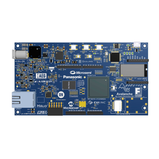
Microsemi Avalanche
Future Electronics Microsemi Avalanche Manuals
Manuals and User Guides for Future Electronics Microsemi Avalanche. We have
1
Future Electronics Microsemi Avalanche manual available for free PDF download: User Manual
Future Electronics Microsemi Avalanche User Manual (30 pages)
Brand:
Future Electronics
| Category:
Motherboard
| Size: 1 MB
Table of Contents
Table of Contents
2
1 Revision History
6
Revision 1.0
6
2 Getting Started
7
Box Contents
7
Block Diagram
8
Board Overview
8
Figure 1 - Avalanche Block Diagram
8
Figure 2 - Avalanche Board
9
Table 1 - Avalanche Board Components
10
Powering up the Board
11
3 Installation and Setting
12
Software Settings
12
Hardware Settings
12
Power Supply Leds
12
Test Points
12
Power Sources
12
Table 2 - Power Supply Leds
12
Table 3 - I/O Voltage Rails
12
Figure 3 - Avalanche Board Power Supply Block Diagram
13
4 Board Components and Operations
14
DDR3 Memory Interface
14
SPI Serial Flash
14
Figure 4 - DDR3 Memory Interface
14
Transceivers
15
XCVR0 Interface
15
Figure 5 - SPI Flash Interface
15
Figure 6 - XCVR0 Interface
15
XCVR1 Interface
16
125-Mhz Transceiver Reference Clock
16
Figure 7 - XCVR1 Interface
16
Figure 8 - Transceiver Reference Clock
16
Microsemi PHY (VSC8531)
17
Figure 9 - PHY Interface
17
Panasonic Wi-Fi (PAN9320)
18
Figure 10 - PAN9320 Block Diagram
18
Figure 11 - Wi-Fi Interface
18
Table 4 - Wi-Fi Leds
18
Microchip ADC (MCP3903)
19
Programming
19
Ftdi
19
Figure 12 - ADC Interface
19
System Reset
20
50-Mhz Oscillator
20
Figure 13 - FTDI Interface
20
Figure 14 - Reset Circuit
20
User Interface
21
User Leds
21
Push-Button Switches
21
Figure 15 - 50-Mhz Clock Oscillator
21
Table 5 - User Leds
21
Table 6 - Push-Button Switches
21
Live Probes Header
22
SFP+ Connector
22
Figure 16 - Live Probes Header
22
Arduino™ Compatible Expansion Headers
23
Table 7 - J11 SFP+ Connector Pinout
23
Table 8 - J3 Arduino Connector Pinout
23
Table 9 - J4 Arduino Connector Pinout
23
Mikrobus™ Compatible Expansion Headers
24
Table 10 - J6 Arduino Connector Pinout
24
Table 11 - J7 Arduino Connector Pinout
24
Table 12 - J8 Mikrobus Connector Pinout
24
PMOD™ Compatible Expansion Connector
25
Table 13 - J9 Mikrobus Connector Pinout
25
Table 14 - J5 PMOD Connector Pinout
25
5 Pin List
26
6 Board Component Placement
27
Figure 17 - Silkscreen Top View
27
Figure 18 - Silkscreen Botton View
27
7 Demo Design
28
8 Appendix: Programming Polarfire FPGA Using the On-Board Flashpro5
29
Figure 19 - Selecting the On-Board Flashpro5
29
Advertisement
Advertisement
Related Products
Future Electronics Microsemi
Future Electronics Categories
Motherboard
GPS
Computer Hardware
Controller
More Future Electronics Manuals
Login
Sign In
OR
Sign in with Facebook
Sign in with Google
Upload manual
Upload from disk
Upload from URL