Sign In
Upload
Manuals
Brands
Fujitsu Manuals
CD/CDR Drive
MCJ3230AP
Fujitsu MCJ3230AP Manuals
Manuals and User Guides for Fujitsu MCJ3230AP. We have
1
Fujitsu MCJ3230AP manual available for free PDF download: Product Manual
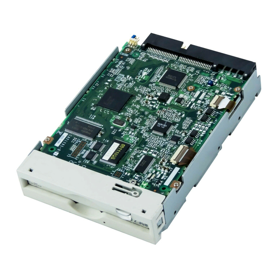
Fujitsu MCJ3230AP Product Manual (199 pages)
Fujitsu Computer Drive User Manual
Brand:
Fujitsu
| Category:
CD/CDR Drive
| Size: 2.32 MB
Table of Contents
Revision History
3
Conventions Used in this Manual
7
Important Alert Items
10
Table of Contents
15
Chapter 1 General Description
27
Figure 1.1 Outer View (with Panel)
32
Figure 1.2 Outer View (Without Panel)
32
Figure 1.3 Optical Disk Drive Configuration
33
Figure 1.4 Control Circuit Section Block Diagram
34
Figure 1.5 System Configuration with One Optical Disk Drive
36
Figure 1.6 System Configuration with Two Optical Disk Drives
36
Table 2.1 Model and Order Number
37
Table 2.2 Specifications
37
Table 2.3 Environmental and Power Requirements
40
Table 2.4 Recommended Optical Disk Cartridge Specifications
43
2.2.2 Optical Disk Cartridge
44
Figure 2.1 Optical Disk Cartridge
44
Table 2.5 Disk Specifications
46
Figure 2.2 Algorithms for Alternate Processing
47
Figure 2.3 Example of Alternate Processing
48
Temperature Measurement Point
49
Figure 3.1 Surface Temperature Measurement Points
50
Temperature Requirements and Measuring Method
51
Air Flow
51
Table 3.1 Temperature Requirements at Measurement Points
51
Temperature Rise under Several Conditions
52
Air Purity
52
Table 3.2 Temperature at each Measuring Point (Reference)
52
Mounting Requirements
53
External Dimensions
53
Figure 3.2 Dimensions
54
Figure 3.3 Dimensions (Without Panel)
55
Figure 3.4 Installation Directions
56
Installation Direction
56
Figure 3.5 Centers of Gravity
57
Mounting Frame Structure
58
Notes on Mounting
58
Figure 3.6 Mounting Frame Structure
58
Figure 3.7 Service Clearance
59
Current Waveform (+5 VDC)
60
Power Supply Requirements
60
Figure 3.8 Current Waveform (+5 VDC)
60
Cable Connections
61
Drive Connectors
61
Figure 3.9 Connector and Terminal Locations
61
Figure 3.10 Cable Connection Diagram
62
Drive Connection
62
Table 3.3 Cable Connector Specifications
62
Jumper Settings
63
Mode Setting
63
Figure 3.11 Jumper Settings at Factory Shipping
63
Figure 3.12 Master Device Setting
63
Figure 3.13 Slave Device Setting
64
Figure 3.14 Cable Select Mode Setting
64
Figure 3.15 Cable Select Examples
65
Notes on Drive Handling
66
Checks before Mounting the Drive
69
Mounting Procedure
69
Cable Connections
69
Operation Confirmation and Preparation for Use after Installation
70
Confirming Initial Operations
70
Connection Check
71
Dismounting Drive
71
CHAPTER 4 Host Interface
73
Table 4.1 Connector Pin Assignments
74
Pin Assignment
74
Table 4.2 Signal Description
76
Table 4.3 I/O Port Functions and Mapping
78
Interface Registers
78
I/O Registers
78
Table 4.4 Bit Definitions of Alternate Status Register
79
ATA Command Register
79
Data Register
79
Table 4.5 Bit Definitions of Device Control Register
79
Table 4.6 Bit Definitions of Drive Address Register
80
Table 4.7 Bit Definitions of ATAPI Byte Count Register
80
Table 4.8 Bit Definitions of ATAPI Block Device Select Register
81
Table 4.9 Bit Definitions of Error Register
81
ATA Features Register
82
Table 4.10 Bit Definitions of ATAPI Features Register
82
ATA Sector Count Register
82
Table 4.11 Bit Definitions of ATAPI Interrupt Reason Register
82
Sector Number Register
83
ATAPI Status Register
83
Bit Definitions of ATAPI Status Register
83
Various Processes
85
Reset Response
85
Signature
86
Defect Sector Management
86
Automatic Alternate Sector Assignment Function
86
Cache Function
87
Data Buffer
87
Read Cache
87
MO Write Cache
88
Media Status Notification Function
88
Power Management Function
89
Power Mode
89
Active Mode
89
Pre-Idle Mode
89
Idle Mode
90
Standby Mode
90
Sleep Mode
90
Standby Timer
90
Power Mode Transition
91
Unsupported Functions
91
Figure 4.1 Power Mode
91
LED Indications
92
Table
92
ATA Commands
93
Table
93
Command Codes and Parameters
93
CHECK POWER MODE (E5H)
94
Table
94
CHECK POWER MODE Command
94
Power Mode Indication
94
EXECUTE DEVICE DIAGNOSTIC (90H)
95
Table
95
DEVICE RESET Command
95
EXECUTE DEVICE DIAGNOSTIC Command
95
Table
96
Self-Diagnosis Detailed Code
96
FLUSH CACHE (E7H)
97
GET MEDIA STATUS (Dah)
97
Table
97
FLUSH CACHE Command
97
GET MEDIA STATUS Command
97
IDENTIFY PACKET DEVICE (A1H)
98
Error Register
98
IDENTIFY PACKET DEVICE Command
98
Table
98
Table
99
Table
100
Table
101
Table
102
Table
103
Table
104
IDLE IMMEDIATE (E1H)
105
NOP (00H)
105
Table
105
IDLE IMMEDIATE Command
105
NOP Command
105
PACKET (A0H)
106
Table
106
PACKET Command
106
SET FEATURES (Efh)
107
Table
107
SET FEATURES Command
107
FR Register Setting Value
107
Transfer Setting Values in the SC Register
108
Table
108
Cylinder Low Register
108
Cylinder High Register
108
SLEEP (E6H)
109
Table
109
SLEEP Command
109
STANDBY IMMEDIATE (E0H)
110
Table
110
STANDBY IMMEDIATE Command
110
Packet Commands
111
Table
111
Packet Command Codes and Parameters
111
ERASE Command
112
Table
112
FORMAT UNIT Command
113
Table
113
FORMAT UNIT Parameter List
113
Defect List Header
113
INQUIRY Command
114
Table
114
INQUIRY Data
115
Table
115
MODE SELECT (6) Command
116
Table
116
Mode Parameters
116
Block Descriptor
117
Mode Parameter Header
117
Mode Parameter List
117
Table
117
Mode Page Format
118
Read-Write Error Recovery Page
118
Table
118
Changeable Values in the Read-Write Recovery Page
119
Default Values for the Read-Write Recovery Page
119
Table
119
Flexible Disk Page
120
Table
120
Table 4.55 Changeable Values in Flexible Disk Page
121
Table 4.56 Default Values in Flexible Disk Page
121
Caching Page
122
Table
122
Table 4.57 Caching Page
122
Table 4.58 Changeable Values in the Caching Page
122
Table 4.59 Default Values for the Caching Page
122
Power Condition Page
123
Table
123
Table 4.60 Power Condition Page
123
Table 4.61 Power Condition Page Variable
123
Table
124
Table 4.62 Power Condition Page Default Value
124
Table 4.63 Verify Control Page
124
Table 4.64 Verify Mode
124
Verify Control Page
124
MODE Select (10) Command
125
Table
125
Table 4.65 Verify Control Page Variable
125
Table 4.66 Verify Control Page Default Value
125
Table 4.67 Mode Select (10) Command
125
Table 4.68 Mode Parameter List
126
Table 4.69 Mode Parameter Header
126
MODE SENSE (6) Command
127
Table 4.70 MODE SENSE (6) Command
127
Table 4.71 Page Control Field
127
Table 4.72 Mode Parameter List
128
Table 4.73 Mode Parameter Header
128
MODE SENSE (10) Command
129
Table 4.74 Block Descriptor
129
Table 4.75 Mode Page Format
129
Table 4.76 MODE SENSE (10) Command
129
Table 4.77 Mode Parameter List
130
Table 4.78 Mode Parameter Header
130
PREVENT/ALLOW MEDIUM REMOVAL Command
131
Table 4.79 PREVENT/ALLOW MEDIUM REMOVAL Command
131
Table 4.80 Response to Prevent/Allow/Eject
131
READ (10) Command
132
READ CAPACITY Command
132
Table 4.81 READ (10) Command
132
Table 4.82 READ CAPACITY Command
132
READ FORMAT CAPACITIES Command
133
Table 4.83 READ CAPACITY Data
133
Table 4.84 READ FORMAT CAPACITIES Command
133
Table 4.85 READ FORMAT CAPACITIES Data Format
133
Table 4.86 Capacity List Header
133
READ DEFECT DATA (10) Command
134
Table 4.87 Current/Maximum Capacity Descriptor
134
Table 4.88 Descriptor Code Definition
134
Table 4.89 READ DEFECT DATA (10) Command
134
Table 4.90 Defect List Format - READ DEFECT DATA (10)
135
Table 4.91 Defect List Header - READ DEFECT DATA (10)
135
Table 4.92 Defect Descriptor
135
READ DEFECT DATA (12) Command
136
Table 4.93 Sector Address Format
136
Table 4.94 READ DEFECT DATA (12) Command
136
Table 4.95 Defect List Format - READ DEFECT DATA (12)
136
READ LONG Command
137
Table 4.96 Defect List Header - READ DEFECT DATA (12)
137
Table 4.97 READ LONG Command
137
RECEIVE DIAGNOSTIC RESULTS Command
138
REQUEST SENSE Command
138
Table 4.98 RECEIVE DIAGNOSTIC RESULTS Command
138
Table 4.99 REQUEST SENSE Command
138
Table 4.100 Request Sense Data
139
Table 4.101 Error Code
139
Table 4.102 Sense Key
140
Table 4.103 Logical Block Address Format
140
Table 4.104 ASC/ASCQ List (1/2)
141
Table 4.105 Format Progress Indication Bytes
142
SEEK Command
143
SEND DIAGNOSTIC Command
143
Table 4.106 SEND DIAGNOSTIC Command
143
Table 4.107 SEEK Command
143
START/STOP UNIT Command
144
Table 4.108 START/STOP UNIT Command
144
Table 4.109 START/STOP/EJECT Processing
144
SYNCHRONIZE CACHE Command
145
Table 4.110 SYNCHRONIZE CACHE Command
145
Table 4.111 TEST UNIT READY Command
145
TEST UNIT READY Command
145
Table 4.112 VERIFY Command
146
Table 4.113 WRITE (10) Command
146
VERIFY Command
146
WRITE (10) Command
146
Table 4.114 WRITE and VERIFY Command
147
WRITE and VERIFY Command
147
Table 4.115 WRITE BUFFER Command
148
WRITE BUFFER Command
148
Table 4.116 WRITE LONG Command
149
WRITE LONG Command
149
Figure 4.2 Register/Pio Data Transfer
150
Register/Pio Data Transfer Timing
150
Timing
150
Table 4.117 Register/Pio Data Transfer Timing Parameters
151
Figure 4.3 Multiword DMA Data Transfer
152
Multiword DMA Data Transfer Timing
152
Table 4.118 Multiword DMA Data Transfer Timing Parameters
153
Figure 4.4 Ultra DMA Data in Transfer (Initialization Timing)
154
Figure 4.5 Ultra DMA Data in Transfer (Continuous Transfer Timing)
154
Ultra DMA Data in Transfer (Continuous Transfer Timing)
154
Figure 4.6 Ultra DMA Data in Transfer (Host Stop Timing)
155
Figure 4.7 Ultra DMA Data in Transfer (Device End Timing)
155
Ultra DMA Data in Transfer (Device End Timing)
155
Figure 4.8 Ultra DMA Data in Transfer (Host End Timing)
156
Ultra DMA Data in Transfer (Host End Timing)
156
Figure 4.10 Ultra DMA Data out Transfer (Continuous Transfer Timing)
157
Figure 4.9 Ultra DMA Data out Transfer (Initialization Timing)
157
Ultra DMA Data out Transfer (Continuous Transfer Timing)
157
Figure 4.11 Ultra DMA Data out Transfer (Device Stop Timing)
158
Ultra DMA Data out Transfer (Device Stop Timing)
158
Figure 4.12 Ultra DMA Data out Transfer (Host Suspend Timing)
159
Ultra DMA Data out Transfer (Host Suspend Timing)
159
Figure 4.13 Ultra DMA Data out Transfer (Device End Timing)
160
Ultra DMA Data out Transfer (Device End Timing)
160
Table 4.119 Ultra DMA Data out Transfer Parameter
161
Power-On and Reset Timing
162
Table
163
CHAPTER 5 Operation and Cleaning
165
Operating Optical Disk Drive
165
Optical Disk Drive
166
Figure 5.1 Optical Disk Drive Front View (with Panel)
166
Note
167
5.1.3 Inserting Cartridge
167
Figure 5.2 Inserting Cartridge
168
Ejecting (Removing) Cartridge
169
Figure 5.3 Removing Cartridge
169
Cleaning Drive
170
Table 5.1 Head Cleaner
170
Optical Disk Cartridge Operation
171
Figure 5.4 Optial Disk Cartridge
171
Write Protect Tab
172
Figure 5.5 Write Protect Tab
172
How to Affix an Index Label on the MO Cartridge (See Figure 5.6)
173
Notes
173
Figure 5.6 How to Stick an Index Label on the MO Cartridge
173
Cleaning Optical Disk Cartridge
175
Cleaning Tool
175
Table 5.2 Cleaning Kit
175
Cleaning Procedure
176
Figure 5.7 Cleaning Procedure (1)
176
Figure 5.8 Cleaning Procedure (2)
177
Figure 5.9 Cleaning Procedure (3)
177
CHAPTER 6 Diagnosis and Maintenance
179
Diagnosis
179
Table 6.1 Self-Diagnostic Function
179
Initial Self-Diagnosis
180
Diagnostic Command
180
Test Program
180
Maintenance Information
181
Figure 6.1 Revision Label
182
Revision Number Indication
182
Figure 6.2 Revision Number Indication
182
Glossary
183
Abbreviations
187
Index
189
Advertisement
Advertisement
Related Products
Fujitsu MCJ3230SS
Fujitsu MCF3064AP
Fujitsu MCM3064AP
Fujitsu MCM3130AP
Fujitsu MCM3064SS
Fujitsu MCP3130SS
Fujitsu MCM3130SS
Fujitsu MCE3064SS
Fujitsu MCF3064SS
Fujitsu MCP3064SS
Fujitsu Categories
Air Conditioner
Laptop
Server
Scanner
Storage
More Fujitsu Manuals
Login
Sign In
OR
Sign in with Facebook
Sign in with Google
Upload manual
Upload from disk
Upload from URL