Sign In
Upload
Manuals
Brands
Fujitsu Manuals
Microcontrollers
MB90931
Fujitsu MB90931 Manuals
Manuals and User Guides for Fujitsu MB90931. We have
1
Fujitsu MB90931 manual available for free PDF download: Hardware Manual
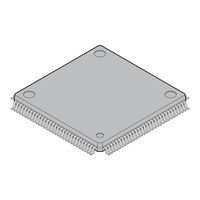
Fujitsu MB90931 Hardware Manual (810 pages)
F2MC-16LX 16-BIT MICROCONTROLLER
Brand:
Fujitsu
| Category:
Microcontrollers
| Size: 9 MB
Table of Contents
Table of Contents
9
Chapter 1 Overview
21
Overview of MB90930 Series
22
Features
23
Block Diagram
25
Package Dimension
26
Pin Assignment
27
Pin Functions
28
I/O Circuit Types
37
Precautions for Handling Device
41
Chapter 2 Cpu
45
Outline of CPU
46
Memory Space
48
Memory Map
50
Addressing
52
Addressing with Linear Scheme
53
Addressing with Bank Scheme
54
Allocation of Multiple-Byte Data in the Memory
56
Registers
58
Dedicated Registers
59
Accumulator (A)
61
Stack Pointers (USP, SSP)
64
Processor Status (PS)
66
Program Counter (PC)
70
Direct Page Register (DPR)
71
Bank Registers (PCB, DTB, USB, SSB, ADB)
72
General-Purpose Register
73
Prefix Codes
75
Chapter 3 Interrupt
81
Outline of Interrupts
82
Interrupt Sources and Interrupt Vectors
84
Interrupt Control Registers and Peripheral Functions
86
Interrupt Control Registers (ICR00 to ICR15)
87
Functions of Interrupt Control Registers
89
Hardware Interrupt
92
Hardware Interrupt Operation
95
Operation Flow of Hardware Interrupt
97
Procedure for Using Hardware Interrupt
98
Multiple Interrupts
99
Hardware Interrupt Processing Time
101
Software Interrupt
102
Interrupt by Extended Intelligent I/O Service (EI 2 OS)
104
Extended Intelligent I/O Service (EI 2 OS) Descriptor (ISD)
106
Extended Intelligent I/O Service (EI 2 OS) Descriptor (ISD) Registers
107
Operation of the Extended Intelligent I/O Service (EI 2 OS)
110
Extended Intelligent I/O Service (EI 2 OS) Procedure
112
Extended Intelligent I/O Service (EI 2 OS) Processing Time
113
Exception Handling Interrupt by Execution of Undefined Instruction
115
Stack Operations of Interrupt Handling
116
Example Program for Interrupt Handling
118
Chapter 4 Reset
123
Outline of Reset
124
Reset Sources and Oscillation Stabilization Wait Time
127
External Reset Pin
129
Reset Operation
130
Reset Source Bit
132
State of each Pin by Reset
136
Chapter 5 Clock
137
Clock
138
Block Diagram of the Clock Generation Block
141
Register in the Clock Generation Block
143
Clock Selection Register (CKSCR)
144
Pll/Sub Clock Control Register (PSCCR)
148
Clock Mode
150
Oscillation Stabilization Wait Time
154
Connection of Oscillator and External Clock
155
Chapter 6 Low-Power Consumption Mode
157
Overview of the Low-Power Consumption Mode
158
Block Diagram of Low-Power Consumption Circuit
161
Low-Power Consumption Mode Control Register (LPMCR)
163
CPU Intermittent Operation Mode
166
Standby Mode
167
Sleep Mode
169
Time-Base Timer Mode
172
Watch Mode
174
Stop Mode
176
State Transition Diagram
179
Pin State in the Standby Mode and at the Time of Reset
181
Notes on Using the Low-Power Consumption Mode
183
Chapter 7 Mode Setting
187
Mode Setting
188
Mode Pins (MD2 to MD0)
189
Mode Data
190
Chapter 8 I/O Ports
193
I/O Ports
194
Assignment of Registers and Pins Shared with External Pins
197
Port 0
199
Port 0 Registers (PDR0, DDR0)
201
Description of Port 0 Operation
202
Port 1
204
Port 1 Registers (PDR1, DDR1)
206
Description of Port 1 Operation
207
Port 2
209
Port 2 Data Register (PDR2, DDR2)
211
Description of Port 2 Operation
212
Port 3
214
Port 3 Registers (PDR3, DDR3)
216
Description of Port 3 Operation
217
Port 4
219
Port 4 Registers (PDR4, DDR4)
221
Description of Port 4 Operation
222
Port 5
224
Port 5 Registers (PDR5, DDR5)
227
Description of Port 5 Operation
228
Port 6
230
Port 6 Registers (PDR6, DDR6, ADER6)
232
Description of Port 6 Operation
233
Port 7
235
Port 7 Registers (PDR7, DDR7, ADER7)
238
Description of Port 7 Operation
240
Port 8
242
Port 8 Registers (PDR8, DDR8, ADER8)
245
Description of Port 8 Operation
247
Port 9
249
Registers for Port 9 (PDR9, DDR9)
251
Description of Port 9 Operation
252
Port C
254
Registers for Port C (PDRC, DDRC)
257
Description of Port C Operation
258
Port D
261
Registers for Port D (PDRD, DDRD)
264
Description of Port D Operation
265
Port E
267
Registers for Port E (PDRE, DDRE)
269
Description of Port E Operation
270
Input Level Select Registers (PIL0 to PIL2)
272
Sample Program for I/O Ports
275
WATCHDOG TIMER/TIME-BASE TIMER/WATCH TIMER (Sub Clock)
277
Outline of Watchdog Timer/Time-Base Timer/Watch Timer
278
Block Diagrams of Watchdog Timer/Time-Base Timer/Watch Timer
279
List of Registers for Watchdog Timer/Time-Base Timer/Watch Timer
280
Watchdog Timer Control Register (WDTC)
281
Time-Base Timer Control Register (TBTC)
283
Watch Timer Control Register (WTC)
285
Operation of Watchdog Timer/Time-Base Timer/Watch Timer
287
Watchdog Timer Operation
288
Operation of Time-Base Timer
290
Operation of Watch Timer
293
Notes on Using the Watchdog Timer/Time-Base Timer
295
Program Example for Watchdog Timer/Time-Base Timer
298
Chapter 10 Input Capture
301
Outline of Input Capture
302
Block Diagram of Input Capture
303
List of Input Capture Registers
305
Detailed Description of the Input Capture Registers
308
Input Capture Edge Register (ICE)
311
Detailed Description of 16-Bit Free-Run Timer Register
315
Description of Operations
320
16-Bit Input Capture
321
16-Bit Free-Run Timer
322
Chapter 11 16-Bit Reload Timer
325
Overview of 16-Bit Reload Timer
326
Configuration of 16-Bit Reload Timer
329
Pins of 16-Bit Reload Timer
331
Registers of 16-Bit Reload Timer
333
Timer Control Status Registers, Upper (TMCSR0H to TMCSR3H)
334
Timer Control Status Registers, Lower (TMCSR0L to TMCSR3L)
336
16-Bit Timer Registers (TMR0 to TMR3)
338
16-Bit Reload Registers (TMRLR0 to TMRLR3)
339
Interrupts of 16-Bit Reload Timer
340
Operation of 16-Bit Reload Timer
341
Internal Clock Mode (Reload Mode)
343
Internal Clock Mode (One Shot Mode)
345
Event Count Mode
347
Notes on Using 16-Bit Reload Timer
349
Sample Program for 16-Bit Reload Timer
350
Chapter 12 Ppg Timer
353
Overview of PPG Timer
354
Block Diagram of PPG Timer
355
Registers of PPG Timer
356
List of PPG Timer Registers
357
Detailed Description of PPG Timer
359
Interrupt of PPG Timer
366
PPG Timer Operation
368
PWM Operation
369
One Shot Operation
371
Interrupt Source and Timing
372
Chapter 13 Real-Time Watch Timer
373
Overview of Real-Time Watch Timer
374
Registers of Real-Time Watch Timer
375
Real-Time Watch Timer Control Register
377
13.2.2 Sub-Second Data Register
379
Second/Minute/Hour/Day Data Registers
380
Interrupts of Real-Time Watch Timer
382
Chapter 14 Delay Interrupt Generation Module
383
Overview of Delay Interrupt Generation Module
384
Operation of Delay Interrupt Generation Module
385
Chapter 15 Dtp/External Interrupt Circuit
387
Overview of Dtp/External Interrupt Circuit
388
Configuration of Dtp/External Interrupt Circuit
390
Pins of Dtp/External Interrupt Circuit
392
Registers of Dtp/External Interrupt Circuit
393
External Interrupt Source Register (EIRR)
394
External Interrupt Enable Register (ENIR)
395
External Interrupt Level Setting Register (ELVRH/ELVRL)
396
Operations of Dtp/External Interrupt Circuit
397
External Interrupt Function
400
DTP Function
401
Notes on Using the Dtp/External Interrupt Circuit
402
Sample Programs of Dtp/External Interrupt Circuit
404
Chapter 16 8-/10-Bit A/D Converter
407
Overview of 8-/10-Bit A/D Converter
408
Block Diagram of 8-/10-Bit A/D Converter
410
Configuration of 8-/10-Bit A/D Converter
413
Upper Bits in the A/D Control Status Register (ADCS1)
416
Lower Bits in the A/D Control Status Register (ADCS0)
421
A/D Data Registers (ADCR0/ADCR1)
423
A/D Setting Registers (ADSR0/ADSR1)
424
Analog Input Enable Registers (ADER6,7,8)
428
Interrupts of 8-/10-Bit A/D Converter
430
Explanation of 8-/10-Bit A/D Converter Operations
431
Single Conversion Mode
433
Continuous Conversion Mode
435
Stop Conversion Mode
437
Conversion Operation by EI os Function
439
A/D Conversion Data Protection Function
440
Precautions When Using 8-/10-Bit A/D Converter
444
Chapter 17 Lin-Uart
445
Overview of LIN-UART
446
Configuration of LIN-UART
449
Pins of LIN-UART
454
LIN-UART Registers
456
Serial Control Register (SCR)
457
LIN-UART Serial Mode Register (SMR)
459
Serial Status Register (SSR)
461
Reception Data Register and Transmission Data Register (RDR/TDR)
463
Extended Status Control Register (ESCR)
465
Extended Communication Control Register (ECCR)
467
Baud Rate Generator Registers 0 and 1 (Bgrn0/Bgrn1)
469
Interrupts of LIN-UART
470
Timing of Reception Interrupt Generation and Flag Set
473
Timing of Transmission Interrupt Generation and Flag Set
475
LIN-UART Baud Rates
477
Setting the Baud Rate
479
Reload Counter
482
Operation of LIN-UART
484
Operation in Asynchronous Mode (Operation Modes 0 and 1)
486
Operation in Synchronous Mode (Operating Mode 2)
490
Operation with LIN Function (Operation Mode 3)
493
Serial Pin Direct Access
496
Bidirectional Communication Function (Normal Mode)
497
Master/Slave Type Communication Function (Multiprocessor Mode)
499
LIN Communication Function
502
Sample Flowcharts for LIN-UART in LIN Communication (Operation Mode 3)
503
Notes on Using LIN-UART
505
Chapter 18 Can Controller
507
Features of CAN Controller
508
Block Diagram of CAN Controller
509
Classification of CAN Controller Registers
510
Control Status Register (CSR)
519
Last Event Indication Register (LEIR)
523
Receive and Transmit Error Counters (RTEC)
525
Bit Timing Register (BTR)
526
Message Buffer Valid Register (BVALR)
529
IDE Register (IDER)
530
Transmission Request Register (TREQR)
531
Transmission RTR Register (TRTRR)
532
Remote Frame Receive Wait Register (RFWTR)
533
Transmission Cancel Register (TCANR)
534
Transmission Complete Register (TCR)
535
Transmission Interrupt Enable Register (TIER)
536
Receive Complete Register (RCR)
537
Remote Request Receive Register (RRTRR)
538
Receive Overrun Register (ROVRR)
539
Receive Interrupt Enable Register (RIER)
540
Acceptance Mask Selection Register (AMSR)
541
Acceptance Mask Registers 0 and 1 (AMR0/AMR1)
543
Message Buffers
545
ID Register X (X = 0 to 15) (Idrx)
546
DLC Register X (X = 0 to 15) (Dlcrx)
550
Data Register X (X = 0 to 15) (Dtrx)
551
CAN Controller Transmission
553
CAN Controller Reception
556
Using CAN Controller
560
Procedure of Transmission Via Message Buffer (X)
561
Procedure of Reception Via Message Buffer (X)
563
Specifying the Multi-Level Message Buffer Configuration
565
18.10 CAN WAKE up Function
567
18.11 Precautions When Using CAN Controller
568
18.12 Sample Program of CAN
569
Chapter 19 Lcd Controller/Driver
571
Overview of LCD Controller/Driver
572
Configuration of LCD Controller/Driver
573
Internal Divided Resistor of LCD Controller/Driver
575
External Divided Resistor of LCD Controller/Driver
577
LCD Controller/Driver Pins
579
Registers of LCD Controller/Driver
581
Lower Bits in the LCD Control Register (LCRL)
582
Upper Bits in the LCD Control Register (LCRH)
584
LCD Output Control Register 2/1 (LOCR2/LOCR1)
586
LCD Output Control Register 3 (LOCR3)
589
LCD Controller/Driver Display RAM
590
Operation of LCD Controller/Driver
594
Output Waveform During the LCD Controller/Driver Operation (1/2 Duty)
596
Output Waveform During the LCD Controller/Driver Operation (1/3 Duty)
599
Output Waveform During the LCD Controller/Driver Operation (1/4 Duty)
602
Chapter 20 Low-Voltage/Cpu Operation Detection Reset Circuit
605
Overview of the Low-Voltage/Cpu Operation Detection Reset
606
Configuration of the Low-Voltage/Cpu Operation Detection
608
Register of the Low-Voltage/Cpu Operation Detection Reset Circuit
610
Operation of the Low-Voltage/Cpu Operation Detection Reset Circuit
612
Notes on Using the Low-Voltage/Cpu Operation Detection Reset Circuit
613
Sample Program for the Low-Voltage/Cpu Operation Detection Reset Circuit
614
Chapter 21 Stepping Motor Controller
615
Overview of Stepping Motor Controller
616
Registers for Stepping Motor Controller
617
PWM Control Register
618
PWM1&2 Compare Registers
620
PWM1&2 Selection Registers
622
Operation of Stepping Motor Controller
625
Cautions When Using Stepping Motor Controller
627
Chapter 22 Sound Generator
629
Outline of the Sound Generator
630
Registers of the Sound Generator
631
Sound Control Register(SGCRH0/SGCRH1, SGCRL0/SGCRL1)
633
Frequency Data Register(SGFR0/SGFR1)
635
Amplitude Data Register(SGAR0/SGAR1)
636
Decrement Grade Register(SGDR0/SGDR1)
637
Tone Count Register(SGTR0/SGTR1)
638
Chapter 23 Rom Mirror Function Select Module
639
Outline of the ROM Mirror Function Select Module
640
ROM Mirror Function Select Register (ROMM)
641
Chapter 24 1M-Bit Flash Memory
643
Overview of 1M-Bit Flash Memory
644
Sector Configuration of 1M-Bit Flash Memory
645
Flash Memory Control Status Register (FMCS)
646
Flash Memory Write Control Registers (FWR0/FWR1)
648
Starting the Flash Memory Automatic Algorithm
653
Confirming the Automatic Algorithm Execution State
654
Data Polling Flag (DQ7)
655
Toggle Bit Flag (DQ6)
656
Timing Limit Exceeded Flag (DQ5)
657
Sector Erase Timer Flag (DQ3)
658
Writing/Erasing Flash Memory
659
Setting Flash Memory to the Read/Reset State
660
Writing Data to Flash Memory
661
Erasing All Data of Flash Memory (Chip Erase)
663
Erasing Arbitrary Data of Flash Memory (Sector Erase)
664
Suspending Sector Erase of Flash Memory
666
Restarting Sector Erase of Flash Memory
667
Flash Security Function
668
Chapter 25 Examples of Serial Programming Connection
669
Basic Configuration for Serial Programming Connection
670
Example of Connection in Single-Chip Mode (Using Power from User System)
674
Example of Connection with Flash Microcontroller Programmer (Using Power from the User System)
676
Chapter 26 Rom Security Function
679
Overview of ROM Security Function
680
Chapter 27 Address Match Detection Function
681
Outline of the Address Match Detection Function
682
Sample Application of the Address Match Detection Function
685
Example of Program Error Correction
687
Example of Correction Processing
688
Appendix
691
APPENDIX A I/O Maps
692
APPENDIX B Instructions
722
Instruction Types
723
Addressing
724
Direct Addressing
726
An Operand Value, Register, or Address Is Specified Explicitly in Direct Addressing Mode
726
Indirect Addressing
732
Execution Cycle Count
740
Effective Address Field
743
How to Read the Instruction List
744
F 2 MC-16LX Instruction List
747
Instruction Map
761
Index
783
Advertisement
Advertisement
Related Products
Fujitsu MB90930 Series
Fujitsu MB90931S
Fujitsu MB90F482B
Fujitsu MB90V485B
Fujitsu MB90487B
Fujitsu MB90F488B
Fujitsu MB90483B
Fujitsu MB90F489B
Fujitsu MB90F428A
Fujitsu MB90427A
Fujitsu Categories
Air Conditioner
Laptop
Server
Scanner
Storage
More Fujitsu Manuals
Login
Sign In
OR
Sign in with Facebook
Sign in with Google
Upload manual
Upload from disk
Upload from URL