Sign In
Upload
Manuals
Brands
Fujitsu Manuals
Air Conditioner
AUXG07-14KVLA
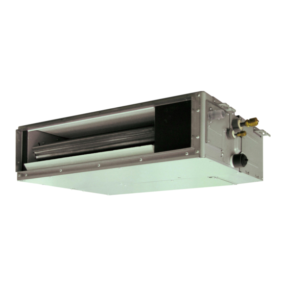
Fujitsu AUXG07-14KVLA Manuals
Manuals and User Guides for Fujitsu AUXG07-14KVLA. We have
3
Fujitsu AUXG07-14KVLA manuals available for free PDF download: Design & Technical Manual
Fujitsu AUXG07-14KVLA Design & Technical Manual (442 pages)
2-unit multi-split type, INDOOR/OUTDOOR
Brand:
Fujitsu
| Category:
Air Conditioner
| Size: 27 MB
Table of Contents
Table of Contents
3
Part 1. Indoor Unit
7
Model Lineup
8
Connectable Indoor Units to each Outdoor Unit
11
Indoor Unit Connection Patterns
12
Specifications
13
Compact Cassette Type
13
Mini Duct Type
14
Slim Duct Type
15
Medium Static Pressure Duct Type
16
Wall Mounted Type
17
Floor Type
33
Wireless LAN Control (for KMCF, KMCG, KMCG-B, KETF, KETF-B, KGTF, KGTG, and KNCA)
34
System Requirement
34
Dimensions
35
Compact Cassette Type
35
Installation Space Requirement
36
Mini Duct Type
37
Maintenance Space Requirement
38
Slim Duct Type
39
Medium Static Pressure Duct Type
41
Rear View
41
Front View
41
Wall Mounted Type
44
Floor Type
59
Installation Space
60
Wiring Diagrams
61
Compact Cassette Type
61
Mini Duct Type and Slim Duct Type
62
Medium Static Pressure Duct Type
63
Wall Mounted Type
64
Floor Type
76
Air Velocity and Temperature Distributions
77
Compact Cassette Type
77
Mini Duct Type
83
Slim Duct Type
91
Wall Mounted Type
99
Floor Type
105
Fan Performance
106
Mini Duct Type
106
Slim Duct Type
114
Medium Static Pressure Duct Type
122
Fan Performance Curve
122
Airflow
126
Compact Cassette Type
126
Mini Duct Type
127
Slim Duct Type
128
Medium Static Pressure Duct Type
129
Wall Mounted Type
130
Floor Type
141
Noise Level Curve
142
Compact Cassette Type
142
Mini Duct Type
144
Slim Duct Type
146
Medium Static Pressure Duct Type
148
Wall Mounted Type
149
Floor Type
157
Sound Level Check Point
159
Electrical Characteristics
162
Input Power
164
Safety Devices
165
External Input and Output
168
12-1.Compact Cassette Type and Medium Static Pressure Duct Type
168
Indoor Unit
169
Input Signal Type
170
External Output
171
Function Setting
174
Operation/Stop Mode
175
Forced Thermostat off
176
Rotary Switch
176
Input Signal
176
Error Status
177
Indoor Unit Fan Operation Status
178
12-2.Mini Duct Type and Slim Duct Type
179
Combination of External Input and Output
181
Control Output Function
183
External Heater Output
184
12-3.Wall Mounted Type (KGTB, KETA, and KETA-B)
185
External Input and Output PCB
186
12-4.Wall Mounted Type (KMTB and KMCC)
195
Control Input (Operation/Stop or Forced Stop)
195
Operation Status Output
198
Error Status Output
199
12-5.Wall Mounted Type (KMCE, KMCF, KMCG, KMCG-B, KMCH, KMCH-B, KETE, KETE- B, KETF, KETF-B, KGTE, KGTF, KGTG, and KGTH)
200
Indoor Unit
201
External Input and Output PCB
202
Input Select
202
Combination of External Input and Output
205
Input Signal Type
206
Control Output Function
211
Output Signal
211
12-6.Floor Type
213
Auxiliary Heater Control
221
Operation
221
Group Connection
222
Remote Controller
224
14-1.Wireless Remote Controller (AR-REW4E, AR-REM4E, AR-REB1E, and AR-REJ1E)
224
Display Panel
225
14-2.Wireless Remote Controller (AR-REW3E)
229
14-3.Wireless Remote Controller (AR-REM7E)
231
14-4.Wireless Remote Controller (AR-RMB1E and AR-RMB1E-B)
233
Remote Controller (UTY-LBTGM: Optional Part)
235
14-6.Wireless Remote Controller (AR-RPF4E)
238
14-7.Wired Remote Controller (UTY-RNNGM: Optional Part)
240
System Diagram
241
Electrical Wiring
241
Wiring Specifications
242
Installation
242
14-8.Wired Remote Controller (UTY-RVRG : Optional Part)
244
System Diagrams
246
Remote Controller Cable
246
Group Control
248
Installation Space
249
On/Off Button
254
Display Panel
254
14-9.Wired Remote Controller (UTY-RLRG: Optional Part)
254
System Diagram
255
14-10.Wired Remote Controller (UTY-RVNGM: Optional Part)
258
Controller Combination
259
Installation Procedures
261
Terminal Screw
263
Tightening Torque
263
14-11.Wired Remote Controller (UTY-RNRGZ*: Optional Part)
266
14-12.Wired Remote Controller (UTY-RCRGZ1: Optional Part)
270
14-13.Simple Remote Controller (UTY-RSNGM: Optional Part)
274
Mode Button
274
Standby Indicator
274
14-14.Simple Remote Controller (UTY-RSRG and UTY-RHRG: Optional Parts)
278
Function Settings
282
15-1.Compact Cassette, Mini Duct, Slim Duct Types Indoor Unit (Setting by DIP Switch)
282
Component Location
282
Dip Switch Setting
283
15-2.Medium Static Pressure Duct Type
284
15-3.Indoor Unit (Setting by Wireless Remote Controller)
285
15-4.Indoor Unit (Setting by Wired Remote Controller)
305
Setting Procedure by Using Wired Remote Controller
308
15-5.Indoor Unit (Setting by Simple Remote Controller)
318
Function Setting List
325
15-6.Function Details
325
Filter Sign
328
Factory Setting
331
Auto Restart
332
15-7.Wired Remote Controller (UTY-RNNGM)
335
Switch Location
335
15-8.Wired Remote Controller (UTY-RVNGM)
337
15-9.Wired Remote Controller (UTY-RLRG)
338
15-10.Wired Remote Controller (UTY-RNRGZ*)
338
15-11.Simple Remote Controller (UTY-RSNGM)
339
Accessories
340
16-1.Compact Cassette Type
340
16-2.Mini Duct Type
341
16-3.Slim Duct Type
342
16-4.Medium Static Pressure Duct Type
343
16-5.Wall Mounted Type
344
16-6.Floor Type
351
Optional Parts
352
17-1.Controllers
352
Wireless Remote Controller
354
17-2.Cassette Grille
358
17-3.Others
359
External Switch Controller
360
Indoor Unit Installation Precautions
367
18-1.Places Where Prohibited for Use
367
18-2.Points to Remember When Installing
367
Part 2. OUTDOOR UNIT (2 UNITS TYPE)
371
Specifications
372
Dimensions
374
Model: AOHG14KBTA2
374
Model: AOHG18KBTA2
375
Installation Space
376
Models: AOHG14KBTA2 and AOHG18KBTA2
376
Space Requirement
376
Single Outdoor Unit Installation
376
Multiple Outdoor Unit Installation
377
Outdoor Units Installation in Multi-Row
378
Refrigerant Circuit
379
Model: AOHG14KBTA2
379
Model: AOHG18KBTA2
380
Wiring Diagram
381
Model: AOHG14KBTA2
381
Model: AOHG18KBTA2
382
Capacity Table
383
Combinations
383
Cooling Capacity
387
Compact Cassette Type
389
Mini Duct Type
390
Slim Duct Type
391
Wall Mounted Type
393
Floor Type
397
Heating Capacity
409
Capacity Compensation Rate for Pipe Length and Height Difference
431
Model: AOHG14KBTA2
431
Model: AOHG18KBTA2
433
Additional Charge Calculation
435
Model: AOHG14KBTA2
435
Refrigerant Charge
435
Model: AOHG18KBTA2
435
Airflow
436
Model: AOHG14KBTA2
436
Model: AOHG18KBTA2
436
Operation Noise (Sound Pressure)
437
10-1.Noise Level Curve
437
10-2.Sound Level Check Point
438
Electrical Characteristics
439
Safety Devices
440
Accessories
441
13-1.Models: AOHG14KBTA2 and AOHG18KBTA2
441
Outdoor Unit Installation Precautions
442
14-1.Places Where Prohibited for Use
442
14-2.Points to Remember When Installing
442
Advertisement
Fujitsu AUXG07-14KVLA Design & Technical Manual (366 pages)
2-unit multi-split type
Brand:
Fujitsu
| Category:
Air Conditioner
| Size: 18 MB
Table of Contents
Table of Contents
3
Part 1. INDOOR UNIT
7
Model Lineup
8
Connectable Indoor Units to each Outdoor Unit
9
Indoor Unit Connection Patterns
10
Specifications
11
Compact Cassette Type
11
Mini Duct Type
12
Slim Duct Type
13
Medium Static Pressure Duct Type
14
Wall Mounted Type
15
Floor Type
19
Wireless LAN Control (for KMCG, KMCG-B, KETF, KETF-B, KGTG, and KNCA)
20
System Requirement
20
Dimensions
21
Compact Cassette Type
21
Mini Duct Type
23
Slim Duct Type
25
Medium Static Pressure Duct Type
27
Wall Mounted Type
30
Floor Type
39
Wiring Diagrams
41
Compact Cassette Type
41
Mini Duct Type and Slim Duct Type
42
Medium Static Pressure Duct Type
43
Wall Mounted Type
44
Floor Type
48
Air Velocity and Temperature Distributions
49
Compact Cassette Type
49
Mini Duct Type
55
Slim Duct Type
63
Wall Mounted Type
71
Floor Type
77
Fan Performance
78
Mini Duct Type
78
Slim Duct Type
86
Medium Static Pressure Duct Type
94
Airflow
98
Compact Cassette Type
98
Mini Duct Type
99
Slim Duct Type
100
Medium Static Pressure Duct Type
101
Wall Mounted Type
102
Floor Type
105
Noise Level Curve
106
Compact Cassette Type
106
Mini Duct Type
108
Slim Duct Type
110
Medium Static Pressure Duct Type
112
Wall Mounted Type
113
Floor Type
120
Sound Level Check Point
122
Electrical Characteristics
125
Safety Devices
126
External Input and Output
127
12-1.Compact Cassette Type and Medium Static Pressure Duct Type
127
12-2.Mini Duct Type and Slim Duct Type
138
12-3.Wall Mounted Type (KMCG, KMCG-B, KETF, KETF-B, and KGTG)
144
12-4.Floor Type
157
Group Connection
166
Remote Controller
167
14-1.Wireless Remote Controller (AR-REW4E and AR-REJ1E)
167
14-2.Wireless Remote Controller (AR-REW3E)
170
14-3.Wireless Remote Controller (AR-REM7E)
172
14-4.Wireless Remote Controller (AR-RMB1E and AR-RMB1E-B)
174
Remote Controller (UTY-LBTYM: Optional Part)
176
14-6.Wireless Remote Controller (AR-RPF4E)
179
14-7.Wired Remote Controller (UTY-RNNYM: Optional Part)
181
14-8.Wired Remote Controller (UTY-RVRY [Optional Part])
184
14-9.Wired Remote Controller (UTY-RLRY: Optional Part)
194
14-10.Wired Remote Controller (UTY-RVNYM: Optional Part)
197
14-11.Wired Remote Controller (UTY-RNRYZ*: Optional Part)
204
14-12.Wired Remote Controller (UTY-RCRYZ1: Optional Part)
207
14-13.Simple Remote Controller (UTY-RSNYM: Optional Part)
211
14-14.Simple Remote Controller (UTY-RSRY and UTY-RHRY: Optional Parts)
214
Function Settings
217
15-1.Compact Cassette, Mini Duct, Slim Duct Types Indoor Unit (Setting by DIP Switch)
217
15-2.Medium Static Pressure Duct Type
219
15-3.Indoor Unit (Setting by Wireless Remote Controller)
220
15-4.Indoor Unit (Setting by Wired Remote Controller)
240
15-5.Indoor Unit (Setting by Simple Remote Controller)
253
15-6.Function Details
260
15-7.Wired Remote Controller (UTY-RNNYM)
268
15-8.Wired Remote Controller (UTY-RVNYM)
270
15-9.Wired Remote Controller (UTY-RLRY)
271
15-10.Wired Remote Controller (UTY-RNRYZ*)
271
15-11.Simple Remote Controller (UTY-RSNYM)
272
Accessories
273
16-1.Compact Cassette Type
273
16-2.Mini Duct Type
274
16-3.Slim Duct Type
275
16-4.Medium Static Pressure Duct Type
276
16-5.Wall Mounted Type
277
16-6.Floor Type
279
Optional Parts
280
17-1.Controllers
280
17-2.Cassette Grille
284
17-3.Others
285
Indoor Unit Installation Precautions
291
18-1.Places Where Prohibited for Use
291
18-2.Points to Remember When Installing
291
Part 2. OUTDOOR UNIT (2 UNITS TYPE)
295
Specifications
296
Dimensions
298
Model: AOEG14KBCA2
298
Model: AOEG18KBCA2
299
Installation Space
300
Models: AOEG14KBCA2 and AOEG18KBCA2
300
Refrigerant Circuit
303
Model: AOEG14KBCA2
303
Model: AOEG18KBCA2
304
Wiring Diagram
305
Model: AOEG14KBCA2
305
Model: AOEG18KBCA2
306
Capacity Table
307
Combinations
307
Cooling Capacity
311
Heating Capacity
333
Capacity Compensation Rate for Pipe Length and Height Difference
355
Model: AOEG14KBCA2
355
Model: AOEG18KBCA2
357
Additional Charge Calculation
359
Model: AOEG14KBCA2
359
Model: AOEG18KBCA2
359
Airflow
360
Model: AOEG14KBCA2
360
Model: AOEG18KBCA2
360
Operation Noise (Sound Pressure)
361
10-1.Noise Level Curve
361
10-2.Sound Level Check Point
362
Electrical Characteristics
363
Safety Devices
364
Accessories
365
13-1.Models: AOEG14KBCA2 and AOEG18KBCA2
365
Outdoor Unit Installation Precautions
366
14-1.Places Where Prohibited for Use
366
14-2.Points to Remember When Installing
366
Fujitsu AUXG07-14KVLA Design & Technical Manual (340 pages)
AIR CONDITIONER 2-unit multi-split type
Brand:
Fujitsu
| Category:
Air Conditioner
| Size: 22 MB
Table of Contents
Table of Contents
3
Part 1. INDOOR UNIT
7
Model Lineup
8
Connectable Indoor Units to each Outdoor Unit
9
Indoor Unit Connection Patterns
10
Specifications
11
Compact Cassette Type
11
Mini Duct Type
12
Slim Duct Type
13
Wall Mounted Type
14
Floor Type
21
Dimensions
22
Compact Cassette Type
22
Mini Duct Type
24
Slim Duct Type
26
Wall Mounted Type
28
Floor Type
38
Wiring Diagrams
40
Compact Cassette Type
40
Mini Duct Type and Slim Duct Type
41
Wall Mounted Type
42
Floor Type
49
Air Velocity and Temperature Distributions
50
Compact Cassette Type
50
Mini Duct Type
56
Slim Duct Type
64
Wall Mounted Type
72
Floor Type
74
Fan Performance
75
Mini Duct Type
75
Slim Duct Type
83
Airflow
91
Compact Cassette Type
91
Mini Duct Type
92
Slim Duct Type
93
Wall Mounted Type
94
Floor Type
99
Noise Level Curve
100
Compact Cassette Type
100
Mini Duct Type
102
Slim Duct Type
104
Wall Mounted Type
106
Floor Type
110
Sound Level Check Point
112
Electrical Characteristics
115
Safety Devices
117
External Input and Output
119
11-1.Compact Cassette, Mini Duct, and Slim Duct Types
119
11-2.Wall Mounted Type (KGTB, KETA, and KETA-B)
125
11-3.Wall Mounted Type (KMTB and KMCC)
135
11-4.Wall Mounted Type (KGTE, KMCE, KETE, and KETE-B)
140
11-5.Floor Type
153
Group Connection
162
Remote Controller
164
13-1.Wireless Remote Controller (AR-REW4E, AR-REM4E, and AR-REB1E)
164
13-2.Wireless Remote Controller (AR-REW3E)
169
13-3.Wireless Remote Controller (AR-REM7E)
171
13-4.Wireless Remote Controller (AR-RMB1E)
173
13-5.Wireless Remote Controller (UTY-LNTY: Optional Part)
175
13-6.IR Receiver Kit with Wireless Remote Controller (UTY-LBTYM: Optional Part)
177
13-7.Wired Remote Controller (UTY-RNNYM: Optional Part)
180
13-8.Wired Remote Controller (UTY-RLRY: Optional Part)
184
13-9.Wired Remote Controller (UTY-RVNYM: Optional Part)
187
13-10.Wired Remote Controller (UTY-RNRYZ*: Optional Part)
195
13-11.Wired Remote Controller (UTY-RCRYZ1: Optional Part)
198
13-12.Simple Remote Controller (UTY-RSNYM: Optional Part)
202
13-13.Simple Remote Controller (UTY-RSRY and UTY-RHRY: Optional Parts)
206
Function Settings
209
14-1.Compact Cassette, Mini Duct, Slim Duct Types Indoor Unit (Setting by DIP Switch)
209
14-2.Indoor Unit (Setting by Wireless Remote Controller)
211
14-3.Indoor Unit (Setting by Wired Remote Controller)
227
14-4.Indoor Unit (Setting by Simple Remote Controller)
238
14-5.Function Details
245
14-6.Wired Remote Controller (UTY-RNNYM)
254
14-7.Wired Remote Controller (UTY-RVNYM)
256
14-8.Wired Remote Controller (UTY-RLRY)
257
14-9.Wired Remote Controller (UTY-RNRYZ*)
257
14-10.Simple Remote Controller (UTY-RSNYM)
258
Accessories
259
15-1.Compact Cassette Type
259
15-2.Mini Duct Type
260
15-3.Slim Duct Type
261
15-4.Wall Mounted Type
262
15-5.Floor Type
266
Optional Parts
267
16-1.Controllers
267
16-2.Cassette Grille
271
16-3.Others
272
Indoor Unit Installation Precautions
278
17-1.Places Where Prohibited for Use
278
17-2.Points to Remember When Installing
278
Advertisement
Advertisement
Related Products
Fujitsu AUXG07KVLA
Fujitsu AUXG07-22KVLA
Fujitsu AUXG07-18KVLA
Fujitsu AUXG09KVLA
Fujitsu AUXG18LRLB
Fujitsu AUXG-KVLA Series
Fujitsu AUXG36KRLB
Fujitsu Cassette AUXG18KRLB
Fujitsu AUXG22KVLA
Fujitsu AUXG30KRLB
Fujitsu Categories
Air Conditioner
Laptop
Server
Scanner
Storage
More Fujitsu Manuals
Login
Sign In
OR
Sign in with Facebook
Sign in with Google
Upload manual
Upload from disk
Upload from URL