Sign In
Upload
Manuals
Brands
FRONTGRADE Manuals
Motherboard
GR716-MINI
FRONTGRADE GR716-MINI Manuals
Manuals and User Guides for FRONTGRADE GR716-MINI. We have
2
FRONTGRADE GR716-MINI manuals available for free PDF download: User Manual
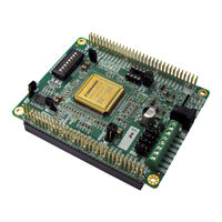
FRONTGRADE GR716-MINI User Manual (30 pages)
Brand:
FRONTGRADE
| Category:
Motherboard
| Size: 1 MB
Table of Contents
Table of Contents
2
Introduction
4
Scope and Purpose of the Document
4
Reference Documents
4
Abbreviations
5
Introduction
6
Overview
6
Figure 3-1: GR716-MINI Development Board
6
Handling
7
Board Design
8
Board Block Diagram
8
Figure 4-1: GR716-MINI Board Block Diagram
8
Board Mechanical Configuration
9
Figure 4-2: GR716-MINI Board Dimensions (Top Side)
9
Figure 4-3: GR716-MINI Board Dimensions (Bottom Side - Expansion Connector)
9
GR716 Microcontroller
10
Figure 4-5: GR716 Microcontroller Block Diagram
10
Memory
11
Figure 4-6: GR716 Package
11
Figure 4-7: SPI Boot Memory Connection
11
Expansion/Interface Connector
12
Figure 4-8: SRAM Signal Connections
12
LVDS Interfaces
13
Figure 4-9: Expansion/Interface Connector
13
Table 1: List of Expansion Connector Signals
13
FTDI Serial to USB Interface
15
Figure 4-10: Block Diagram of FTDI Serial to USB Interface
15
Table 2: FTDI USB-Serial Port Assignment
15
Analog Signals
16
Figure 4-11: MMCX Analog Connector Interface
16
Gpio
17
Table 3: List of GPIO Pins Connected to Expansion Connector
17
Bootstrap Signals
18
Table 4: Bootstrap Resistor Settings
18
Debug Support Unit Interfaces
19
Figure 4-12: Debug Support Unit Connections
19
Oscillators and Clock Inputs
20
Figure 4-13: Board Level Clock Distribution Scheme
20
Power Supply and Voltage Regulation
21
Figure 4-14: Power Regulation Scheme
21
Reset Circuit and Button
22
Watchdog
22
Setting up and Using the Board
23
Table 5: Default Setting of Jumpers
23
Interfaces and Configuration
24
List of Connectors
24
Table 6: List of Connectors
24
Table 7: J1 USB Type Micro B Connector - FTDI Serial Link
24
Table 8: J2,J3,J4,J5 MMCX Miniature Coax Connectors
24
Table 9: Expansion Connector P1 Pin-Out
25
List of Oscillators, Switches and Led's
26
Table 10: List and Definition of Oscillators and Crystals
26
Table 11: List and Definition of PCB Mounted Led's
26
Table 12: List and Definition of Switches
26
Figure 6-1: PCB Top View
27
Figure 6-2: PCB Bottom View
27
Figure 6-3: PCB Top View (Photo)
28
Figure 6-4: PCB Bottom View (Photo)
28
Revision Information
29
Advertisement
FRONTGRADE GR716-MINI User Manual (29 pages)
Brand:
FRONTGRADE
| Category:
Motherboard
| Size: 2 MB
Table of Contents
Table of Contents
2
Introduction
4
Scope and Purpose of the Document
4
Reference Documents
4
Abbreviations
4
Introduction
5
Overview
5
Figure 3-1 GR716-BOARD Development Board
5
Handling
6
Board Design
7
Board Block Diagram
7
Figure 4-1 GR716-BOARD Board Block Diagram
7
Board Mechanical Configuration
8
Figure 4-2 GR616-BOARD Board Dimensions
8
Figure 4-3 GR716-BOARD Mounted on a GR716-CPCI-DEV Carrier Board
9
Figure 4-4 GR716-TEST-MEMORY BOARD
10
Figure 4-5 GR716-TEST-ADCDAC BOARD
10
GR716 Microcontroller
11
Figure 4-6 GR716 Microcontroller Block Diagram
11
Figure 4-7 GR716 Package
11
Memory
12
Figure 4-8 SPI Boot Memory Connectons
12
LVDS Interfaces
13
Gpio
14
Bootstrap Signals
14
Table 1: Bootstrap Resistor Settings
14
Debug Support Unit Interfaces
15
Figure 4-9 Debug Support Unit Connections
15
Figure 4-10 GR716-DSU-USB Adapter
15
Oscillators and Clock Inputs
16
Figure 4-11 Board Level Clock Distribution Scheme
16
Power Supply and Voltage Regulation
17
Figure 4-12 Power Regulation Scheme
18
Figure 4-13 Power Supply Configuration Jumpers
19
Reset Circuit and Button
20
Watchdog
20
Setting up and Using the Board
20
Interfaces and Configuration
21
List of Connectors
21
Table 2: List of Connectors
21
Table 3: J1 Screw Terminal Connector for Input Voltages
21
Table 4: J2 POWER-External Power Connector
21
Table 5: Expansion Connector P1 Pin-Out
22
Table 6: Expansion Connector P2 Pin-Out
22
List of Oscillators, Switches and Led's
23
Table 7: List and Definition of Oscillators and Crystals
23
Table 8: List and Definition of PCB Mounted Led's
23
Table 9: List and Definition of Switches
23
Table 10: Definition of Switch S1 Functions (Refer to [RD1])
23
Figure 6-1 PCB Top View
24
Figure 6-2 PCB Bottom View
25
Figure 6-3 PCB Top View (Photo)
26
Figure 6-4 PCB Bottom View (Photo)
27
Advertisement
Related Products
FRONTGRADE GR716-BOARD
FRONTGRADE GR716-CPCI-DEV
FRONTGRADE GR-CPCI-GR716-DEV
FRONTGRADE GR740-MINI
FRONTGRADE Categories
Motherboard
Computer Hardware
More FRONTGRADE Manuals
Login
Sign In
OR
Sign in with Facebook
Sign in with Google
Upload manual
Upload from disk
Upload from URL