Sign In
Upload
Manuals
Brands
Fronius Manuals
Portable Generator
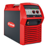
TransSteel 3500 Rob
Fronius TransSteel 3500 Rob Manuals
Manuals and User Guides for Fronius TransSteel 3500 Rob. We have
1
Fronius TransSteel 3500 Rob manual available for free PDF download: Operating Instructions Manual
Fronius TransSteel 3500 Rob Operating Instructions Manual (104 pages)
MIG/MAG
Brand:
Fronius
| Category:
Portable Generator
| Size: 4 MB
Table of Contents
Table of Contents
5
Safety Rules
9
General
9
Proper Use
9
Environmental Conditions
10
Obligations of the Operator
10
Obligations of Personnel
10
Mains Connection
10
Protecting Yourself and Others
11
Danger from Toxic Gases and Vapours
11
Danger from Flying Sparks
12
Risks from Mains Current and Welding Current
12
Meandering Welding Currents
13
EMC Device Classifications
14
EMC Measures
14
EMF Measures
14
Specific Hazards
15
Factors Affecting Welding Results
16
Danger from Shielding Gas Cylinders
16
Danger from Escaping Shielding Gas
17
Safety Measures at the Installation Location and During Transport
17
Safety Measures in Normal Operation
17
Commissioning, Maintenance and Repair
18
Safety Inspection
18
Disposal
19
Safety Symbols
19
Data Protection
19
Copyright
19
General Information
21
General
23
Device Concept
23
Requirements
23
Functional Principle
23
Application Areas
23
Warning Notices on the Device
24
Options
25
General
25
Machine Interface
25
Gas Test Button
25
Gas Preheater CO2 Connection
25
VRD: Safety Function
26
VRD: Safety Principle
26
Control Elements and Connections
27
Synergic Control Panel
29
General
29
Safety
29
Service Parameters
32
Keylock
32
Connections, Switches and Mechanical Components
34
Tst 3500 Rob / 5000 Rob Power Source
34
Installation and Commissioning
35
Minimum Equipment Needed for Welding Task
37
General
37
MIG/MAG Welding, Gas-Cooled
37
MIG/MAG Welding, Water-Cooled
37
Before Installation and Commissioning
38
Utilisation for Intended Purpose Only
38
Setup Regulations
38
Mains Connection
38
Connecting the Mains Cable
39
General
39
Stipulated Mains Cables and Strain Relief Devices
39
Fitting the Europe Strain-Relief Device
40
Fitting the Strain-Relief Device for Canada / US and Tst 5000 MV Europe
41
Generator-Powered Operation
42
Start-Up
43
Information on System Components
43
Tst 3500 Rob / 5000 Rob Start-Up
44
Fitting the System Components (Overview)
44
Strain Relief Device
44
Connecting the Interconnecting Hosepack
44
Connecting the Gas Cylinder
45
Creating a Grounding (Earthing) Connection, Connecting the Welding Torch
45
Other Activities
45
Welding
47
Power Limitation
49
Safety Function
49
MIG/MAG Modes
50
General Remarks
50
Symbols
50
2-Step Mode
50
Special 4-Step Mode
51
MIG/MAG Welding
52
Safety
52
General Tasks before MIG/MAG Welding
52
Overview
52
MIG/MAG Standard Synergic Welding
53
General
53
Corrections During Welding
54
MIG/MAG Standard Manual Welding
55
General
55
Available Parameters
55
Corrections During Welding
56
MMA Welding
57
Safety
57
Preparations
57
Corrections During Welding
58
Hotstart Function
58
Anti-Stick Function
58
Saving and Retrieving Operating Points
60
General
60
Saving Operating Points
60
Retrieving Operating Points
60
Deleting Operating Points
60
Retrieving Operating Points on the Up/Down Welding Torch
60
Setup Settings
63
Setup Menu
65
General Remarks
65
Entering/Exiting the Setup Menu
65
Setup Parameters for MIG/MAG Standard Manual Welding
66
Setup Parameters for MIG/MAG Standard Synergic Welding
68
Setup Parameters for MMA Welding
69
Welding Parameters for "Special 4-Step Mode" in the Mode Setup Menu
70
Setup Menu - Level 2
71
Level 2 Setup Menu
71
Welding Parameters for MIG/MAG Welding in the Setup Menu Level 2
72
Parameters for Manual Metal Arc (MMA) Welding in the Setup Menu Level 2
73
Measuring Welding Circuit Resistance R
74
General
74
Measure the Welding Circuit Resistance R
74
Displaying Welding Circuit Inductivity L
75
General
75
Laying the Hosepacks Correctly
75
Troubleshooting and Maintenance
77
Troubleshooting
79
General
79
Safety
79
Power Source - Troubleshooting
79
Displayed Service Codes
81
Care, Maintenance and Disposal
87
General
87
Safety
87
At Every Start-Up
87
Every 2 Months
87
Every 6 Months
87
Disposal
87
Technical Data
88
Special Voltages
88
Explanation of the Term "Duty Cycle
88
Tst 3500 Rob
88
Tst 5000 Rob
89
Tst 3500 MV Rob
90
Tst 5000 MV Rob
91
Welding Program Tables
93
Transsteel 3500 Euro Welding Program Tables
93
Transsteel 5000 Euro Welding Program Tables
94
Transsteel 3500 US Welding Program Tables
95
Transsteel 5000 US Welding Program Tables
96
Quick Reference
97
Appendix
99
Spare Parts List: Tst 3500 Rob, Tst 5000 Rob
100
Advertisement
Advertisement
Related Products
Fronius TransPocket 3500 TIG
Fronius TransPocket 3500 RC
Fronius TransPocket 3500 VRD
Fronius TransPocket 3500 MVm
Fronius TransTig 3000 Comfort
Fronius TransTig 3000 Job
Fronius TransSteel 2700c
Fronius TransSteel 2700c MV
Fronius TransSteel 5000 Rob
Fronius TransSteel 3500c
Fronius Categories
Inverter
Welding System
Welding Accessories
Battery Charger
Measuring Instruments
More Fronius Manuals
Login
Sign In
OR
Sign in with Facebook
Sign in with Google
Upload manual
Upload from disk
Upload from URL