Sign In
Upload
Manuals
Brands
Frenic Manuals
Inverter
5000VG7S Series
Frenic 5000VG7S Series Manuals
Manuals and User Guides for Frenic 5000VG7S Series. We have
1
Frenic 5000VG7S Series manual available for free PDF download: Instruction Manual
Frenic 5000VG7S Series Instruction Manual (98 pages)
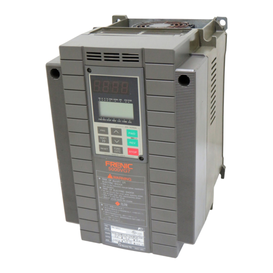
High-Performance, Vector Control Inverter
Brand:
Frenic
| Category:
Inverter
| Size: 3 MB
Table of Contents
Instruction Manual
1
Instructions on Installation
2
Instructions on Use
2
Safety Instructions
2
Instructions on Wiring
3
Instructions on Operation
4
Instructions on Maintenance, Inspection, and Replacement
5
Warning Label Position
6
Warning Label Position for Inside the Inverter
7
Tightening Torque and Wire Range
9
Applicable Main Circuit Motor/Wire Size
14
Table of Contents
15
1 Before Use
16
Inspection after Receipt
16
External View of the Product
16
Handling of the Product
17
Removal of Surface Cover
17
Removal of KEYPAD Panel
17
Transportation
18
Storage Conditions
18
Extended Storage
18
Temporary Storage
18
2 Installation and Connection
19
Operating Conditions
19
Output Reduction Rates at Higher Altitudes
19
Installation Procedure
20
External Cooling System Diagram
20
Number and Size of Fixing Screws
21
Electric Connections
22
Basic Connections
22
Basic Wiring Diagram
23
Wiring of Main Circuit and Grounding Terminals
24
Terminals
25
Connection Diagrams
27
Example of Wiring of Inverter Combined with PWM Converter
29
Reconnection of Fan Power Switching Connector
29
Power Switching Connectors (18.5Kw or Higher Inverters Only)
30
Wiring of Control Terminals
31
Input Terminals
32
Digital Input Terminals (FWD, REV, X1-X9, PLC, and CM)
33
Miscellaneous Terminals
33
Transistor Output Terminals (Y1-Y4 and CME)
33
Wiring of Control Circuits
33
Routing Inverter Control Circuit Leads
34
Securing Inverter Control Circuit Leads
34
Terminal Arrangement Chart
35
Main Circuit Terminals
35
Control Circuit Terminals
36
3 Test Run
37
Preliminary Check and Preparation
37
Operating Methods
37
Motor Rotating Directions
37
4 Keypad Panel
39
Appearance of KEYPAD Panel
39
Functions of Operation Keys
40
Alarm Mode
41
Keypad Operation System (Hierarchical Structure of LCD Screens)
42
During Normal Operation
42
When an Alarm
42
Raised Occurs
42
Outline of Indications on Different Screens
43
Program Mode
43
Program Mode
44
5 Function Selection
45
Fundamental Functions
46
6 List of Inverter Protective
48
Extension Terminal Functions
48
Control Functions of Frequency
50
Motor Parameters
51
High Performance Functions
52
Alternative Motor Parameters
53
Optional Functions
54
Lift Function
55
User Functions
55
Serial Communication Functions
56
Monitoring Functions
56
List of Inverter Protective Functions
57
Function Description (Arranged by Function)
59
If You Think Defective
59
What You Should Check First
59
Have You Entered the Speed Reference?
60
Checks Using Flowchart
61
Malfunctions Not Followed by Alarms
61
Vector Control and Sensorless Vector Control Troubles
61
Motor Runs but Does Not Change Speed
62
Motor Runs Only at Low Speed
63
Motor Presents Hunting
64
Motor Is Unstable on Acceleration/Deceleration
64
Motor Generates Abnormal Heat
65
Motor Runs Inversely against Direction Reference
65
V/F Control Troubles
66
Motor Does Not Run
66
Motor Stalls During Acceleration
68
Malfunctions Followed by Alarms
69
Overcurrent
69
Ground Fault
71
Fuse Blown
71
Overvoltage
72
Undervoltage
74
Inverter Internal Overheat and Overheating at Heat Sink
75
External Alarm
76
Motor Overheat
77
Inverter Overload and Motor Overload
78
PG Error
78
Overspeed
79
NTC Thermistor Disconnection
80
Charging Circuit Error
80
Memory Error
81
KEYPAD Panel Communication Error
81
CPU Error and A/D Converter Error
82
Output Wiring Error
82
RS485 Communication Error
83
Input Phase Loss
84
DB Resistor Overheating
84
Operation Procedure Error
85
8 Maintenance and Inspection
86
Daily Inspection
86
Periodical Inspection
86
Periodical Inspection List
87
Rough Estimate of Life Expectancy Using Maintenance Information
88
Measurement of Main Circuit Electrical Quantity
89
Meters for Measuring Main Circuit
89
Insulation Test
90
Parts Replacement
90
Inquiries about Products and
90
Inquiries about Products and Product Guarantee
90
RFI Filter
91
Recommended Installation
91
9 Compliance with Standards
91
Compliance with Ul/Cul Standards
91
Overview
91
Notes
91
Compliance with European Standard
91
Compliance with EMC Standard
91
RFI Filter Dimension List
93
Diagrams
94
Advertisement
Advertisement
Related Products
Frenic Categories
Inverter
More Frenic Manuals
Login
Sign In
OR
Sign in with Facebook
Sign in with Google
Upload manual
Upload from disk
Upload from URL