Table of Contents
Advertisement
Quick Links
5000VG7S Series
INSTRUCTION MANUAL
High-Performance, Vector Control Inverter
CT Use (150%)
200V Series
0.75kW/FRN0.75VG7S-2
90kW/FRN90VG7S-2
VT Use (110%)
200V Series
1.5kW/FRN0.75VG7S-2
110kW/FRN90VG7S-2
HT Use (200%/170%)
200V Series
3.7kW/FRN3.7VG7S-2
55kW/FRN55VG7S-2
400V Series
3.7kW/FRN3.7VG7S-4
400kW/FRN400VG7S-4
400V Series
5.5kW/FRN3.7VG7S-4
500kW/FRN400VG7S-4
400V Series
3.7kW/FRN3.7VG7S-4
55kW/FRN55VG7S-4
CAUTION
Read all operating instructions
before installing, connecting
(wiring), operating, servicing, or
inspecting the inverter.
Ensure that this instruction manual
is made available to the final user
of the inverter.
Store this manual in a safe,
convenient location.
The product is subject to change
without prior notice.
Advertisement
Table of Contents

Summary of Contents for Frenic 5000VG7S Series
-
Page 1: Instruction Manual
5000VG7S Series INSTRUCTION MANUAL High-Performance, Vector Control Inverter CT Use (150%) 200V Series 400V Series 0.75kW/FRN0.75VG7S-2 3.7kW/FRN3.7VG7S-4 90kW/FRN90VG7S-2 400kW/FRN400VG7S-4 VT Use (110%) 200V Series 400V Series 1.5kW/FRN0.75VG7S-2 5.5kW/FRN3.7VG7S-4 110kW/FRN90VG7S-2 500kW/FRN400VG7S-4 HT Use (200%/170%) 200V Series 400V Series 3.7kW/FRN3.7VG7S-2 3.7kW/FRN3.7VG7S-4 55kW/FRN55VG7S-2... - Page 2 Instructions Thank you for purchasing our FRENIC5000VG7S series inverter. This product is used to drive a 3-phase induction motor at variable speed. As incorrect use of this product may result in personal injury and/or property damage, read all operating instructions before using. As this manual does not cover the use of function cords and option cards, etc., refer to FRENIC5000VG7S Users Manual.
- Page 3 · Do not hold or carry this inverter by the surface cover. Inverter may be dropped causing injury. · Ensure that the inverter and heat sink surfaces are kept free from foreign matter (lint, paper dust, small chips of wood or metal chips), as fire or accident may result. ·...
- Page 4 Instructions on operation · Be sure to install the surface cover before turning on the power (closed). Do not remove the cover while power to the inverter is turned on. Electric shock may occur. · Do not operate switches with wet hands, as electric shock may result. ·...
- Page 5 Instructions on maintenance, inspection, and replacement · Wait a minimum of five minutes (15kW or less) or ten minutes (18.5kW or more) after power has been turned off (open) before starting inspection. (Also confirm that the charge lamp is off and that DC voltage between terminals P(+) and N(-) does not exceed 25V.) Electric shock may result.
- Page 6 Warning Label Position Inverter with a small capacity (15kW or lower) Inverter with a middle capacity (18.5kW or higher)
- Page 7 Warning Label Position for Inside the Inverter...
- Page 8 Compliance with UL/cUL Standards 1. Overview The UL standard is an abbreviation for Underwriters Laboratories Inc. and is a safety standard for preventing fires and other accidents, and protecting users, servicemen, and general people in the United States. The cUL standard is a standard which the UL constituted to meet the CSA standard. Products approved by the cUL standard are as valid as produces approved by the CSA standard.
- Page 9 Tightening torque and wire range 1. 60℃/75℃ copper wire CT/HT Use Required torque [lb-inch](N . m) Wire range [AWG] (mm 2 ) Inverter type Auxiliary Auxiliary Voltage FRN□ Main L1/R,L2/S, P1,P(+) P(+),DB, Ground control- Control U,V,W control- Control VG7S-2/4 terminal L3/T N(-) power...
- Page 10 VT Use Required torque [lb-inch](N . m) Wire range [AWG] (mm 2 ) Inverter type Auxiliary Auxiliary Voltage FRN□ Main L1/R,L2/S, P(+),DB, Ground control- Control U,V,W P1,P(+) control- Control VG7S-2/4 terminal L3/T N(-) power power 0.75 14 (2.1) 12 (3.3) (2.1) (2.1) 8 (8.4)
- Page 11 2. 90℃ copper wire CT/HT Use Required torque [lb-inch](N . m) Wire range [AWG] (mm 2 ) Inverter type Auxiliary Auxiliary Voltage FRN□ Main L1/R,L2/S, P1,P(+) P(+),DB, Ground control- Control U,V,W control- Control VG7S-2/4 terminal L3/T N(-) power power 0.75 14 (2.1) 14 (2.1) 14 (2.1)
- Page 12 VT Use Required torque [lb-inch](N . m) Wire range [AWG] (mm 2 ) Inverter type Auxiliary Auxiliary Voltage FRN□ Main L1/R,L2/S, P(+),DB, Ground control- Control U,V,W P1,P(+) control- Control VG7S-2/4 terminal L3/T N(-) power power 0.75 14 (2.1) 14 (2.1) 14 (2.1) 10 (5.3) 31.
- Page 13 Compliance with European Standard The CE marking presented on Fuji products is related to the Council Directive 89/336/EEC and the Low Voltage Directive 73/23/EEC for the Electromagnetic Compatibility (EMC) in Europe. Compliant standards ・ ・ ・ ・ EN 61800-3: 1997 ・...
- Page 14 Table 1-2 Applicable main circuit motor/wire size for compliance to Low Voltage Directive(400V series) Fuse/MCCB Tightening torque [N.m] Recommended wire size [mm Rated current [A] L1/R,L2/SL3/T ( G) Inverter type FRN□ With Without With Without 3.7 3.7VG7S-4(CT/HT) (2.5) 5.5 3.7VG7S-4(VT) 5.5 5.5VG7S-4(CT/HT) 7.5 5.5VG7S-4(VT) 7.5 7.5VG7S-4(CT/HT)
-
Page 15: Function Description
Contents Instructions Safety Instructionss 8. Maintenance and Inspection 1. Before Use ・・・・ ・・・・・・・・・・・・・・・・・・・・・・ 8-1 Daily Inspection ・・・・・・・・・・・・・・・・・・・ 8-1 1-1 Inspection After Receipt ・・・・・・・・・・・・ 1-1 8-2 Periodical Inspection ・・・・・・・・・・・・・・ 8-1 1-2 External View of the Product ・・・・・・・・ 1-1 8-3 Measurement of Main Circuit 1-3 Handling of the Product ・・・・・・・・・・・・... -
Page 16: Before Use
1. Before Use 1-1 Inspection After Receipt Unpackage the product and perform the following checks. If the product is found to have a fault, please contact the dealer from which you purchased the product or the nearest sales office of Fuji Electric. (1) Read the nameplate to check that the product is the same thing as ordered. -
Page 17: Handling Of The Product
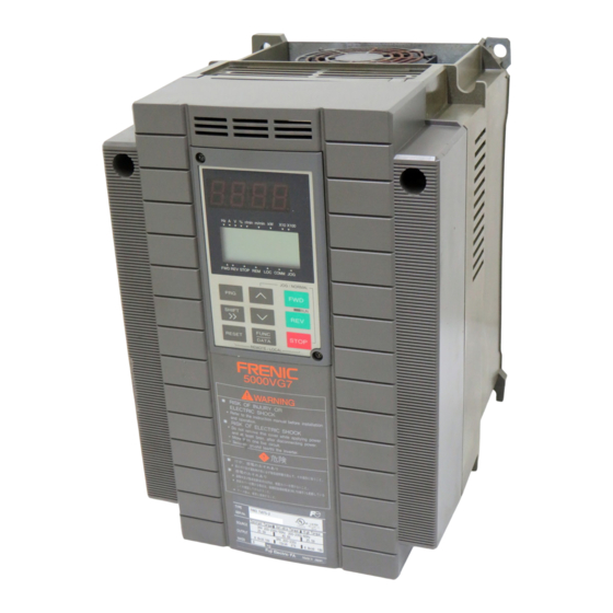
1-3 Handling of the Product (1) Removal of Surface Cover Loosen the surface cover fixing screws. Remove the cover by pulling the top of the cover as shown in Figure 1-3-1. Figure 1-3-1 Removal of Surface Cover (15kW or lower) Remove the six surface cover fixing screws. -
Page 18: Temporary Storage
1-4 Transportation Always hold the body during transportation. Do not hold the cover or any other part. Doing so may break or fall the product. When using a hoist or crane to transport a product with lifting holes, hang hooks and ropes to the holes. 1-5 Storage Temporary Storage Store the product under the conditions specified on Table 1-5-1. - Page 19 2. Installation and Connection 2-1 Operating Conditions Install the product under the conditions specified in Table 2-1-1. Table 2-1-1 Operating Conditions Item Requirement Place Indoor Ambient -10 to +50°C temperature Relative humidity 5% to 95% (no condensation allowed) Atmosphere The product should not be exposed to dust, direct sunlight, corrosive gas, oil mist, vapor, waterdrops, or air containing much salt.
-
Page 20: Installation Procedure
2-2 Installation Procedure (1) Install the product onto a rigid structure in the vertical direction with the letters, FRENIC5000 VG7S, seen from the front and fix with specified bolts. Do not install upside down or in the horizontal direction. Failure to do so may lead to injury. (2) The inverter generates heat during operation. - Page 21 To externally cool a 18.5kW or higher inverter, relocate the upper and lower mounting legs as shown in Figure 2-2-3. Remove the mounting leg fixing screws, relocate the legs, and fix with casing fixing screws. (The casing fixing screws cannot be directly used for some models. See the following table.) The mounting leg fixing screws become unnecessary after the legs are relocated.
-
Page 22: Electric Connections
2-3 Electric Connections Removing the surface cover exposes the terminal blocks. Correctly wire them after reading the following instructions. 2-3-1 Basic Connections (1) Connect power supply leads to the main circuit power terminals, L1/R, L2/S, and L3/T. Connecting any power supply lead to another terminal may fail the inverter. Check that the supply voltage does not exceed the permissible limit indicated on the nameplate, etc. - Page 23 Basic Wiring Diagram Figure 2-3-1 Basic Wiring Diagram...
- Page 24 2-3-2 Wiring of Main Circuit and Grounding Terminals Table 2-3-1 Functions of Main Circuit and Grounding Terminals Terminal symbol Terminal name Description L1/R, L2/S, L3/T Main circuit power input terminals Connected with three-phase power source. U, V, W Inverter output terminals Connected with three-phase motor.
- Page 25 (2) Inverter output terminals (U, V, and W) 1) Connect three-phase motor leads to the inverter output terminals, U, V, and W with care not to connect a wrong phase. 2) Do not connect a phase advancing capacitor or surge absorber (suppressor) to the inverter output terminals.
- Page 26 (3) Auxiliary control power input terminals (R0 and T0) If the magnetic contactor in the power supply circuit to the inverter is turned off (open) when the protection circuit is activated, the inverter control power supply is shut off. As a result, alarm outputs (30A, B, and C) are no longer retained and indications on the KEYPAD panel go away.
- Page 27 (5) Braking resistor connecting terminals (P(+) and DB) The optional braking resistor may be externally DC reactor Braking resistor DB (DCR) mounted. It is required when the inverter is operated frequently or under heavy inertia. (CM) (THR) 1) Connect the braking resistor terminals, P(+) and DB, to the inverter terminals, P(+) and DB.
- Page 28 (7) Inverter grounding terminals ( z G) The inverter grounding terminals, z G, must be grounded to ensure your safety and for noise measures. The Technical Standards for Electric Equipment requires metallic frames of electric equipment be grounded to prevent disasters such as electric shock and fire. Connect the terminals as described below. 1) Connect to type D grounded poles for 200V series or type C grounded poles for 400V series according to the Technical Standards for Electric Equipment.
- Page 29 CN RXTX CN RXTX Figure 2-3-7 Reconnection of Fan Power Switching Connector 18.5kW or higher PWM converter (RHC series) P(+) Earth leakage Magnetic Filter breaker contactor L1/R L2/S Power L3/T source N(-) Inverter unit DB P1 P(+) N(-) L1/R L2/S L3/T CN RXTX Reconnect CN RXTX...
- Page 30 The switching connectors are mounted in the power PC board at the top of the control circuit PC board. CN UX CN RXTX When removing either connector, hold the top of the jaw Note: between fingers to release the latch and remove by pulling upward.
- Page 31 2-3-3 Wiring of Control Terminals Functions of the control circuit terminals are described in Table 2-3-4. Each control terminal should be wired in different ways, depending on its setting. Table 2-3-4 Terminal Terminal name Function symbol Potentiometer power supply Supplies power (+10Vdc) to speed setting POT (1-5kW). Voltage input Controls the speed according to the external analog input voltage command.
- Page 32 Transistor output 1 Outputs signals such as Running, Speed equivalence, Overload early warning, ... and z as transistor outputs from inverter to specified ports. For details, see 2.3.2 'Functions of Terminals'. Transistor output 2 <Transistor Output Circuit Specifications> Transistor output 3 Item min.
- Page 33 (2) Digital input terminals (FWD, REV, X1-X9, PLC, and CM) 1) The digital input terminals such as FWD, REV, and X1- X9 are generally turned on/off between the CM terminal. If turned on/off using an external power source and open collector outputs from the programmable logic controller, the terminals may malfunction due to current leak from the external power source.
- Page 34 Figure 2-3-13 Figure 2-3-14 Routing Inverter (18.5 kW or Securing Inverter (18.5 kW or Higher) Control Circuit Leads Higher) Control Circuit Leads 2) FRN132VG7S-4 to FRN160VG7S-4 (a) Pull the wiring out along the left side panel as shown in Figure 2-3-15. (b) Tie leads with bands (Insulock, for example) and secure with cable tie holders on the beams on the way outward.
-
Page 35: Main Circuit Terminals
2-3-4 Terminal Arrangement Chart l Main circuit terminals FRN 0.75~7.5VG7S-2 FRN 37~55VG7S-2 FRN 3.7~7.5VG7S-4 FRN 75~110VG7S-4 FRN 11~15VG7S-2 FRN 75VG7S-2 FRN 11~15VG7S-4 FRN 90VG7S-2 FRN 18.5~22VG7S-2 FRN 18.5~22VG7S-4 FRN 132~220VG7S-4 FRN 30VG7S-2 FRN 280, 315VG7S-4 FRN 30~55VG7S-4 R0 T0 L1/R L1/R L1/R L1/R... - Page 36 l Control circuit terminals Screw size : M3 2-18...
-
Page 37: Test Run
3. Test Run 3-1 Preliminary Check and Preparation U, V, W Perform the following checks before starting operation. (1) Check that the inverter is correctly wired. Most importantly, the inverter output terminals, U, V, and W should not be connected to a power source and the earth terminal should be correctly grounded. - Page 38 If the inverter is found to normally function in the test run, start regular operation. · If any abnarmal condition is observed with the inverter or motor, immediately stop and locate the cause (see 'Troubleshooting'). · Even after the inverter stops outputting, touching any of the inverter output terminals, U, V, and W may lead to electric shock if a voltage is continuously applied to the main circuit power terminals, L1/R, L2/S, and L3/T, and auxiliary control power terminals, R0 and T0.
- Page 39 4. KEYPAD Panel · If the user set the function codes wrongly or without completely understanding this user’s manual, the motor may rotate with a torque or at a speed not permitted for the machine. Accident or injury may result. ·...
- Page 40 (A) LED monitor: Four-digit 7-segment display Used to display various items of monitored data such as setting frequency, output frequency and alarm code. (B) Auxiliary information indication for LED monitor: Selected units or multiple of the monitored data (on the LED monitor) are displayed on the top line of the LCD monitor.
-
Page 41: Alarm Mode
4-2 Alarm Mode Alarm detection order Alarm code Number of successive When a single alarm occurs, the 1=xxx xxx occurrences alarm mode screen appears Alarm name xxxxxxxxxxxxx where the content of the alarm is PRGðPRG MENU indicated. Operational instruction RESETðRESET When multiple alarms occur at the same time, the contents of the alarms can be checked using the Ù... -
Page 42: During Normal Operation
4-3 KEYPAD Operation System (Hierarchical Structure of LCD Screens) 4-3-1 During Normal Operation The basic KEYPAD operation system (hierarchical structure of screens) is illustrated below. FUNC FUNC 1500 1500 1500 1500 DATA DATA Operation Program Detailed mode screen menu screen information Function screen... - Page 43 Outline of Indications on Different Screens Screen name Description Operation mode You can change motor speed or switch LED monitor when this screen is shown on KEYPAD during normal operation. Program menu Function menu is shown on this screen for your selection. Select a desired (Program mode) function from menu and press FUNC...
-
Page 44: Program Mode
4-3-3 Program Mode The KEYPAD operation (hierarchical structure of screens) in the program mode is illustrated below. Program mode FUNC 1500 DATA Function menu Ù,Ú : Selects a code : Selects a directory FUNC RESET : Saves data FUNC DATA >>... -
Page 45: Function Selection
5. Function Selection · When the retry function is selected, the inverter may restart automatically after tripping. (Design the machine to ensure personal safety in the event of restart) Accident may result. · When the torque limiting function is selected, operating conditions may differ from preset conditions (acceleration/deceleration time or speed). - Page 46 Underline indicates a factory setting. F: Fundamental Functions Items without underline have different factory settings according to capacity. Communication Communication address address Fcode Function name Setting range Fcode Function name Setting range Link number Link number number number 80( 50 h) Data 0 to 1 95( 5F h) Motor sound 0 to 3...
- Page 47 Underline indicates a factory setting. Items without underline have different factory settings according to capacity. Communication Communication address address Fcode Function name Setting range Fcode Function name Setting range Link number Link number number number h) LED monitor -999.00 to 1.00 to 999.00 3Eh 108( 6C h) ASR1 (I-gain) 0.010 to 0.200 to1.000 s coefficient...
- Page 48 Underline indicates a factory setting. E: Extension Terminal Functions Items without underline have different factory settings according to capacity. Communication Communication address address Fcode Function name Setting range Fcode Function name Setting range Link number Link number number number 10Ch 131( 83 h) X13 terminal 0 to 25 to 63 101h 120( 78 h) X1 terminal 0 to 63...
- Page 49 Underline indicates a factory setting. Items without underline have different factory settings according to capacity. Communication Communication address address Fcode Function name Setting range Fcode Function name Setting range Link number Link number number number 11Dh 146( 92 h) PG pulse 0 to 9 133h h) Ai3 function...
- Page 50 Underline indicates a factory setting. Items without underline have different factory settings according to capacity. C: Control Functions of Frequency Communication address Fcode Function name Setting range Communication Link number number address Fcode Function name Setting range 145h h) AO1 function 0 to 1 to 31 Link number selection...
- Page 51 Underline indicates a factory setting. Items without underline have different factory settings according to capacity. P: Motor Parameters Communication address Fcode Function name Setting range Communication Link number number address Fcode Function name Setting range 22Eh h) Acceleration 0.01 to 5.00 to 99.99s Link number time 2 number...
- Page 52 Underline indicates a factory setting. Items without underline have different factory settings according to capacity. H: High Performance Functions Communication address Fcode Function name Setting range Communication Link number number address Fcode Function name Setting range 411h h) Operation 0.0 to 30.0 s Link number command number...
- Page 53 Underline indicates a factory setting. Items without underline have different factory settings according to capacity. Communication Communication address address Fcode Function name Setting range Fcode Function name Setting range Link number Link number number number 428h h) RS485 0 to 1 to 2 447h h) Reserved 2 0 to 6...
- Page 54 Underline indicates a factory setting. Items without underline have different factory settings according to capacity. O: Optional Functions Communication address Fcode Function name Setting range Communication Link number number address Fcode Function name Setting range 51Ah h) M2-R2 0.010 to 5.000 Link number correction number...
- Page 55 Underline indicates a factory setting. Items without underline have different factory settings according to capacity. Communication Communication address address Fcode Function name Setting range Fcode Function name Data setting range Link number Link number number number 627h h) UPAC memory 00 to 1F B1Ch h) USER P28 -32768 to 32767...
- Page 56 Function codes “S” and “M” are codes to access the inverter Underline indicates a factory setting. Items without underline have different factory settings according to capacity. through links (RS485, T-Link, SX communication, field bus, etc). You cannot use them with the KEYPAD panel. Communication address Though you can access the codes “F”...
- Page 57 6. List of Inverter Protective Functions · The motor coasts when an alarm is issued. Install a brake on the driven machine side if you need to stop the motor. An accident may occur. · When you reset the inverter while applying the operation command, the motor restarts suddenly. Make sure the operation command is turned off before you restart.
- Page 58 Related Function Description Display function code Inter-inverter Activated when a communication error occurs in an inter-inverter communication communication using the high-speed serial cards (optional). error IPM error Activated when the self cut-off function of the IPM operates due to an overcurrent or overheat.
-
Page 59: If You Think Defective
7. Function Description (Arranged by Function) 7-1 If You Think Defective · After the inverter protective function was activated and you removed the cause, if you reset the alarm while the operation command has been set to ON, the inverter restarts. Reset the alarm after you confirm the operation command has been set to OFF. - Page 60 (3) Have you entered the speed reference? 1500 Confirm the speed reference (N*) on the "Operation monitor" when you have directed the speed reference by the KEYPAD panel, external analog input, or N*=´´´´´ r/m through the link (T-Link or RS485) or the UPAC. If the "N*" is blank, the inverter N =´´´´´...
-
Page 61: Checks Using Flowchart
7-2 Checks Using Flowchart 7-2-1 Malfunctions not Followed by Alarms (1) Vector control and sensorless vector control 1) Motor does not run. Are charge lamp and Is circuit breaker or Turn on circuit breaker Motor does not run. LCD of KEYPAD magnetic contactor or magnetic contactor. - Page 62 2) Motor runs but does not change speed Is the maximum speed Motor runs but does set to too low Rewrite data according not change speed. (code F03, A06, or to specification. A40)? Is speed limiter ∧ ∨ activated to adjust speed. (code F76 to F78)? YES ...
- Page 63 3) Motor runs only at low speed Motor runs at low speed roughly equivalent to slip frequency and does not accelerate. Continued operation presents alarm trip OL1, 2, or 3. Is sensoless control (code P01 or A01) selected? Is data of PG pulse Rewrite data according number correct to motor PG.
- Page 64 4) Motor presents hunting Change data of Motor presents hunting. function code P02 to match. Do motor parameters (function code P and Is motor dedicated to A) match companion VG7? motor? Execute motor parameter tuning (function code H01). Did you adjust constants of speed control system Adjust constants...
- Page 65 6) Motor generates abnormal heat Change data of function code P02 Motor generates to match. abnormal heat. Do motor parameters Is motor dedicated to (function code P and A) VG7? match companion motor? Execute motor parameter tuning Does motor operate at very (function code H01).
- Page 66 (2) V/f control 1) Motor does not run. Are charge lamp Is circuit breaker or Turn on circuit Motor does not run. (CHG) and LCD of magnetic contactor breaker or magnetic KEYPAD panel ON? turned on? contactor. Check for low voltage, Is voltage on main phase loss, Remove cause of...
- Page 67 2) Motor runs but does not change speed Motor runs but does Is the maximum speed Increase setting. Specify speed. not change speed. set to low? Can you press KEYPAD panel ∧ ∨ change speed? Which means do you use to set speed? Analog input Does speed signal...
- Page 68 3) Motor stalls during acceleration Is acceleration time Motor stalls during (function code F07, Increase acceleration. C46, C56 or C66) acceleration time. short? Is moment of inertia Do you use special- of motor or load Contact FUJI. purpose motor? large? Use thicker wiring Does motor terminal Reduce moment of...
- Page 69 7-2-2 Malfunctions Followed by Alarms (1) Overcurrent 1) Vector control and sensorless vector control Is the carrier frequency setting Over current IPM Error Specify the carrier frequency setting between 2 and 15kHz? between 2 and 15kHz. Is inverter output wiring (U, V, W) short-circuited to ground? Eliminate ground fault.
- Page 70 2) V/f control Over current IPM Error On deceleration. At constant speed. On accelerating, Eliminate short-circuit Is motor connector terminal (U, V, W) short-circuited or short-circuited to ground? or ground fault. Decrease load or Is load too heavy? increase inverter capacity.
- Page 71 (2) Ground fault · Eliminate the cause before turn on the power. You may start fire. Is inverter output wiring (U, V, W) Ground fault short-circuited to ground? Eliminate ground fault. (Disconnect output wiring and make sure no continuity with ground). Is inverter inside wiring short-circuited You must replace motor.
- Page 72 (4) Overvoltage 1) Vector control and sensorless vector control Overvoltage Is power supply voltage within Decrease power supply voltage specification? lower than maximum specification. Is inverter output wiring (U, V, W) short-circuited to ground? Eliminate short-circuit or grand fault. (Disconnect output wiring and make sure no continuity with ground).
- Page 73 2) V/f control Overvoltage On acceleration. On deceleration. At constant speed. Decrease power supply voltage lower Is power supply voltage within specification? than maximum specification. Does overvoltage occur on sudden removal of load? Is DC link circuit voltage in main circuit higher than protection Inverter fault or level on activation? malfunction due to...
- Page 74 (5) Undervoltage Undervoltage Is "Restart mode after momentary power failure (function code F14)" selected? NO Did power failure (momentary power Reset fault to restart operation. failure included) happen? NO Are there device fault or defective Replace defective device and connection in power supply circuit? adjust wiring.
- Page 75 (6) Inverter internal overheat and overheating at heat sink · Heatsink becomes very hot and do not tough it. You may get burnt. Overheating Inverter internal overheat IPM error at heat sink Is load too heavy? Decrease load. Is inverter ambient Reduce ambient temperature within temperature down...
- Page 76 (7) External alarm Related codes: E01 to E14 External alarm Is alarm terminal of external device Connect alarm terminal. connected to digital When you do not want to input terminal do so, change definition of (X terminal) to which digital input terminal External fault [THR] (X terminal).
- Page 77 (8) Motor overheat Related codes: Cooling fan fault is Motor overheat E30, E31, E32, and P30 suspected. Contact FUJI. Is motor cooling fan Is input voltage of cooling running? fan within specification? Review power supply system. Is air passage of cooling fan stuffed? Remove obstacle.
- Page 78 (9) Inverter overload and motor overload Inverter overload Speed disagreement Motor overload OL1, OL2, and OL3 Do electronic thermal Disable electronic thermal relay characteristics relay and connect external match motor overload thermal relay. characteristics? Are data for electronic thermal relay (function code F10 to 12, A32 to Specify correct level.
- Page 79 (11) Overspeed Overspeed Does speed Increase speed present overshoot regulator gain. at high speed? Is droop control used? Is H28 droop gain Decrease H28 droop gain. too large? Use function code P02 to select corresponding motor. Inverter specifies VG7 motor parameters automatically.
- Page 80 (12) NTC thermistor disconnection NTC thermistor disconnection Specify "Thermistor Is motor provided with selection (function code P30, thermistor? A31 or A47)" again. Is motor thermistor signal cable Connect following disconnected wiring diagram. (THC-TH1)? Is motor ambient Review operation temperature low environment.
- Page 81 (14) Memory error (Er1) Review the function data before you turn off the power when the memory error occurs. When the data are correct, the error is limited to data in the back up memory. Only if you can use "All save" to save data without reoccurence of Memory error, you can operate the inverter.
- Page 82 (16) CPU error and A/D converter error CPU error A/D converter error Is there short circuit on PCB? Treat defective part. Is dust attached on PCB? Inverter fault is suspected. Contact FUJI. (17) Output wiring error Output wiring error Is inverter output Connect following wiring (U, V, W) wiring diagram.
- Page 83 (18) RS485 communication error RS485 communication error Disable "No response error Do you direct operation detection time" setting. command through RS485? Does inverter Is "No response error communicate regularly in detection time" (function code specified time? H38) setting disabled? Use maintenance Is communication line Review information of KEYPAD...
- Page 84 (19) Input phase loss · Turn on the power after you eliminate faults. You may start fire. · You can change the setting for the function code E45 to 1* to change the detection sensitivity of the input phase loss alarm. Change the parameter along with the application of the DC reactor (optional, standard for 75 kW or more models).
- Page 85 (21) Operation procedure error Operation procedure error Did you execute tuning Follow tuning procedure. (H01)? Follow restriction Are options installed? of options. Contact FUJI. (22) Others The following alarms are related to options. See User’s Manual for details. Er4 : Network error. When T-Link, SX bus or field bus option is installed. ErA : UPAC error.
-
Page 86: Maintenance And Inspection
8. Maintenance and Inspection Proceed with daily inspection and periodic inspection to prevent malfunction and ensure long-term reliability. Note the following: 8-1 Daily Inspection During operation, a visual inspection for abnormal operation is completed externally without removing the covers The inspections usually cover the following: (1) The performance (satisfying the standard specification) is as expected. - Page 87 Table 8-2-1 Periodical inspection list Check parts Check items How to inspect Evaluation Criteria Environment 1) Check the ambient temperature, 1) Conduct visual inspection 1) The specified standard humidity, vibration, atmosphere (dust, and use the meter. value must be satisfied. gas, oil mist, water drops).
- Page 88 * Estimation of life expectancy based on maintenance information The maintenance information is stored in the inverter KEYPAD panel and indicates the electrostatic capacitance of the main circuit capacitors and the life expectancy of the electrolytic capacitors on the control PC board and of the cooling fans.
- Page 89 8-3 Measurement of Main Circuit Electrical Quantity The indicated values depend on the type of meter because the harmonic component is included in the voltage and current of the main circuit power (input) and the output (motor) side of the inverter. When measuring with a meter for commercial power frequency use, use the meters shown in Table 8.3.1.
-
Page 90: Insulation Test
8-4 Insulation Test Avoid testing an inverter with a megger because an insulation test is completed at the factory. If a megger test must be completed, proceed as described below. Use of an incorrect testing method may result in product damage. -
Page 91: Rfi Filter
9. Compliance with Standards 9-1 Compliance with UL/cUL Standards 9-1-1 Overview The UL standard is an abbreviation for Underwriters Laboratories Inc. and is a safety standard for preventing fires and other accidents, and protecting users, servicemen, and general people in the United States. The cUL standard is a standard which the UL constituted to meet the CSA standard. - Page 92 4) Use shield wires to connect the output lines to the motor. Use as short wires as possible. Connect the earth to the earth terminals on both the motor and the inverter. Electrically connect the shield wires such that the shield of the shield wires completely fills the periphery of the holes at the entrance to the control panel.
- Page 93 Table 9-1 RFI Filter Dimension List Ferrite ring (number) External Installation Applicable Rated Maximum Filter Filter type dimension dimension Control inverter type current rating installation Main circuit Communi- terminal L,W,H[mm] Y,X[mm] cable cation cable cable FRN3.7VG7S-4(CT/HT/VT) 290x70 275x45 M6(4) FS5941-40-47 FRN5.5VG7S-4(CT/HT/VT) x185 FRN7.5VG7S-4(CT/HT/VT)
- Page 94 (FS5941-40-47) Figure 9-1 (FS5941-60-52,FS5941-86-52) Figure 9-2...
- Page 95 19.5 (ZCAT2032-0930) (ACL-74B) Figure 9-3 Dimension [mm] Filter type RF3100-F11 RF3180-F11 (RF3100-F11, RF3180-F11) Figure 9-4...
- Page 96 (RF3280-F11, RF3400-F11) Figure 9-5 (RF3880-F11) Figure 9-6 (F200160) Figure 9-7...
- Page 97 Metal control panel RCD or RFI filter Inverter Power MCCB Shield wires supply L1/R L2/S L3/T PE PE The shield of the shield wires is connected to the earth on the motor, and fills the hole on the control panel Motor for electrical shielding.
Need help?
Do you have a question about the 5000VG7S Series and is the answer not in the manual?
Questions and answers