Sign In
Upload
Manuals
Brands
FreeFlight Manuals
Avionics Display
81440
FreeFlight 81440 Manuals
Manuals and User Guides for FreeFlight 81440. We have
1
FreeFlight 81440 manual available for free PDF download: Component Maintenance Manual With Illustrated Parts List
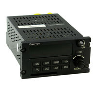
FreeFlight 81440 Component Maintenance Manual With Illustrated Parts List (186 pages)
Receiver/Display Unit
Brand:
FreeFlight
| Category:
Avionics Display
| Size: 4 MB
Table of Contents
Table of Contents
59
Introduction
63
Table Intro-1
63
Table Intro-2
63
Receiver Display Unit
63
Figure Intro-1 Hazardous Material Warning
65
Figure Intro-2 Caution Label
65
Table Intro-3
65
Description and Operation
67
Physical Description
67
Figure 1 2101 I/O Plus Receiver Display Unit
67
System Description
68
Table 1 Leading Particulars
68
Functional Description
69
RDU Operation
69
Figure 2 2101 I/O Plus System
70
Front Panel Layout and Description
71
Figure 3 2101 I/O Plus to Aircraft Interface
71
Internal Annunciators
72
LED Display
72
Mode Keys
72
Power Switch
72
Figure 4 Front Panel Functionality
74
Function Keys
74
Built-In-Test
75
Selector Knobs
75
RDU Circuit Card Assemblies
76
Power Supply CCA (A1)
76
Synchro Power/Filter CCA (A3/A2)
76
Interface CCA (A4)
76
GPS Sensor CCA (A5)
76
Processor Board CCA (A6)
76
Display Assembly CCA (A7)
76
Figure 5 Power Supply CCA (A1)
77
Figure 6 Synchro Power/Filter CCA (A3/A2) (Preferred)
78
Table 2 ARINC 429 Input Devices
79
Figure 7 Interface CCA (A4)
80
Table 3 DADS Digital Input
81
Table 4 AHRS Digital Inputs
81
Table 6 Fuel Digital Inputs
82
Table 8 ARINC 429 Output Parameters
82
Table 9 ARINC 429 VDL Output Parameters
84
Table 10 ARINC 743 TAWS Output Parameters
85
Table 11 30212 Hardware Configuration
86
Table 12 84588 Hardware Configuration
86
Figure 8 GPS Sensor CCA (A5)
87
Figure 9 Processor Board CCA (A6)
91
Figure 10 Display Assembly CCA (A7)
92
Testing and Fault Isolation
93
Task
93
Equipment and Materials
93
Test Procedure
93
Fault Isolation Procedure
93
Table 101-A Essential Test Equipment
94
Table 101-B Option 1 Test Equipment
94
Table 101-C Option 2 Test Equipment
94
Table 101-D Required Software
95
Table 101-E Software Configuration
95
Figure 101-AATP Test Equipment Interconnect
96
Table 101-FUUT Display
100
Table 101-GAIO Test Points
103
Table 101-H Test Points
103
Table 101-I Discrete Field Display
104
Table 101 Final Test Procedure
105
Table 101-J Reference Field Display
105
Table 101-K Channel Display
105
Table 101-L Specs.dat File List
110
Auxiliary Output Tests
111
Table 102 Test to Fault Isolation Cross Reference
112
Figure 116 Auxiliary Input Tests
112
Figure 101 Set up
113
Figure 102 Key Test
114
Figure 103 Power up
115
Figure 104 Software Configuration
116
Figure 105 System Configuration
117
Figure 106 Save Waypoint
120
Figure 107 Power Interrupt Test
121
Figure 108 Button Light Tests
122
Figure 109 Knob Input Tests
124
Figure 110 Display Tests
126
Figure 111 Display Intensity Tests
127
Figure 112 Audio Output Tests
128
Figure 113 No. 1 CDI Test
129
Figure 114 No. 2 CDI Test
130
Figure 115 External Lamps and Flags Test
131
Figure 117 Miscellaneous Output Tests
135
Figure 119 GPS Receiver Tests
143
Figure 120 Serial Port 2 Tests
144
Figure 121 Serial Port 1 Tests
148
Figure 122 Data Card Tests
151
Figure 123 Analog Converter Tests
152
Figure 124 Real-Time Clock Tests
154
Figure 125 User Waypoint Entry
155
Disassembly
157
Task
157
Equipment and Materials
157
Equipment
157
Materials
157
Procedures
157
Upper Case Removal
157
Lower Case Removal
157
Circuit Card Assembly Stack Removal
158
Table 301 CCA/IPL Cross Reference
158
Cleaning
159
Task
159
Equipment and Materials
159
Equipment
159
Materials
159
Procedures
159
Clean External Parts
160
Clean Electrical Parts
160
Clean Glass Parts
160
Clean Mechanical Parts
160
Check
161
Task
161
Equipment and Materials
161
Procedures
161
Examine
161
Make Sure
161
Check Lithium Battery
162
Repair
163
Task
163
Equipment and Materials
163
Equipment
163
Materials
163
Precautions for Lithium Batteries
164
How to Prepare for Maintenance
164
Warning Label on the Battery Container
164
Replacement Procedure
164
Discard Procedure
164
Procedures
164
Special Repair Procedures
164
Paint Touch-Up Procedures
165
Table 601 Paint Touch-Up
165
ASSEMBLY (Including Storage)
167
Task
167
Equipment and Materials
167
Equipment
167
Materials
167
Procedures
167
Circuit Card Assembly Stack
167
Cca A5
167
Cca A4
167
Cca A1
168
Lower Case Installation
168
Upper Case Installation
168
Figure 701 Control Cable Connection
168
Storage
169
Task
169
Equipment and Materials
169
Figure 702 Filter/Power Cable Connection
169
Procedures
170
Special Tools, Fixtures, and Equipment
171
Task
171
Table 901 Software by Release Date
171
Illustrated Parts List
173
Introduction
173
How to Find a Part
173
Contents of Illustrated Parts List
173
Equipment Designator Index
173
Numerical Index
173
Parts List
173
Supplier Codes
174
Abbreviations and Symbols
175
Abbreviations
175
Table 1001 List of Suppliers
176
Table 1002 Equipment Designator Index
177
Figure 1001
181
Table 1004 Parts
182
Figure 1002
185
Table 1005
186
Advertisement
Advertisement
Related Products
FreeFlight 86943-00
FreeFlight 87098-00
FreeFlight 87098-10
FreeFlight 87098-00-FX00
FreeFlight 87098-10-FX10
FreeFlight 87098-00-FR00
FreeFlight 87098-10-FR10
FreeFlight 87099 Series
FreeFlight 87099-01
FreeFlight 87099-11
FreeFlight Categories
Receiver
Measuring Instruments
Transceiver
Transmitter
Avionics Display
More FreeFlight Manuals
Login
Sign In
OR
Sign in with Facebook
Sign in with Google
Upload manual
Upload from disk
Upload from URL