Sign In
Upload
Manuals
Brands
frako Manuals
Controller
38-00404
frako 38-00404 Manuals
Manuals and User Guides for frako 38-00404. We have
1
frako 38-00404 manual available for free PDF download: Operating Manual
frako 38-00404 Operating Manual (72 pages)
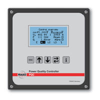
Power Quality Controller, Reactive Power Control Relay
Brand:
frako
| Category:
Controller
| Size: 1.84 MB
Table of Contents
Table of Contents
2
1 Safety
6
Objective
6
Safety Instructions
6
Intended Use
7
Improper Use
8
Repair
8
Symbols Used
8
2 Technical Data
9
3 Instrument Description
12
Function
12
Regeneration
12
4 Mounting the Instrument
13
Suitable Location
13
Installing the Instrument
13
Figure 1 PQC Dimensions in MM
13
5 Installation
15
Electrical Connections
15
Earth Connection
17
Supply Voltage
17
Voltage Measurement
18
Current Measurement
19
Output Relays (Control Outputs)
21
Connection Diagrams of All PQC Instrument Types 5.7.1 Connection Diagram: Version PQC 1202401-XX
22
Figure 2 Connection Diagram for PQC 1202401-XX
22
Connection Diagram: Version PQC 1202403-XX
23
Figure 3 Connection Diagram for PQC 1202403-XX
23
Connection Diagram: Version PQC 0602401-XX
24
Figure 4 Connection Diagram for PQC 0602401-XX
24
Connection Diagram: Version PQC 1204801-XX
25
Figure 5 Connection Diagram for PQC 1204801-XX
25
Connection Diagram: Version PQC 1204803-XX
26
Figure 6 Connection Diagram for PQC 1204803-XX
26
Connection Diagram: Version PQC 0614801-XX
27
Figure 7 Connection Diagram for PQC 0614801-XX
27
Options for Connecting the aux Power Supply for PQC XXX480X-XX Versions
28
Connection Diagram for 400/415 V Networks with no Neutral Conductor
28
Connection Diagram for 690 V Networks with a Neutral Conductor
28
Figure 8 Part of the Connection Diagram for 400 /415 V Networks with no Neutral
28
Figure 9 Part of the Connection Diagram for 690 V Networks with a Neutral Conductor
28
6 Commissioning (Initial Start-Up)
29
Alarm Function
29
List of Alarms and Messages
29
Safety Precautions before Start-Up
30
Functional Checkout
30
Configuration
30
Automatic Commissioning
30
Automatic Connection Identification
30
Figure 10 PQC Start Screen (Firmware Version Number May be Different)
30
Automatic Identification of the Connected Capacitor Stages
31
Table 1 Connection Types for Current Transformers in L1, L2 and L3
31
Calculation of C/K
32
Table 2 C/K Settings at 400 V AC and 50 Hz
32
7 Description of the Menu
33
Table 3 Key Functions
33
Menu Overview
34
Figure 11 Menu Structure 1
34
Figure 12 Menu Structure 2
35
Figure 13 Menu Structure 3
35
8 Main Menu
36
Figure 14 Main Menu 1/3
36
Figure 15 Main Menu 2/3
36
Figure 16 Main Menu 3/3
36
Figure 17 Changing the Working Language
37
Language Selection on Start-Up
37
PQC Initial Start-Up
37
Figure 18 Identification: Stage + Connection
38
Figure 19 Identification: Connection
38
Figure 20 Identification: Connection Submenu
38
Figure 21 Identification: Stage
38
Figure 22 Identification: Stage Submenu
38
Figure 23 Identification: Manual
38
Figure 24 Identification: Manual Submenu
38
Figure 25 Connection Identification Started
39
Figure 26 Capacitor Stage Identification Started
39
Figure 27 Start-Up Completed
39
PQC Overview
39
Start-Up
39
Displayed Parameters
40
Figure 28 PQC Overview L1 (1-Phase)
40
Figure 29 PQC Overview L1 (3-Phase)
40
Figure 30 Capacitor Stage Statuses (1-Phase, 6 Stages)
40
Figure 31 Capacitor Stage Statuses (3-Phase, 12 Stages)
40
Control Diagram
41
Figure 32 Control Diagram
41
Figure 33 Control Diagram with Additional Information
41
Figure 34 Zoomed in on Control Diagram
41
Scale
41
Figure 35 Manual Control
42
Figure 36 Manual Control Enabled
42
Figure 37 Manual Control: Switch out Stages
42
Manual Control
42
Figure 38 Manual Control: Stages Menu
43
Figure 39 Example of a Selected Stage
43
Stages Menu
43
Figure 40 Message on Failed Attempt to Switch in a Stage
44
Figure 41 Settings
44
Settable Control Profiles
44
Settings
44
Parallel Shift -1.0
44
Figure 42 Control Profiles
45
Figure 43 Control Profile Parameters
45
Typical Control Profile Applications
45
Figure 44 Control Response after Setting Target Cos Φ = 1, Limitation = 0, Parallel Shift = 0
46
Setting Target Cos
46
Parallel Shift
46
Parallel Shift
47
Limitation L
48
Figure 51 Phase L1 Is the Control Phase
50
General Settings
50
Selecting the Control Phase
50
Switching Delay
50
Capacitor Stages Menu
51
Figure 52 General Settings Menu
51
Figure 53 Capacitor Stages
52
Figure 54 Set Limits 1/2
52
Figure 55 Set Limits 2/2
52
Setting Alarm Limits
52
Detection of Voltage Blackout (Sag)
53
Figure 56 Change Set Limit for Switching Cycle Counter
53
Overcurrent
53
Alarm Management
54
Figure 57 Alarm Management
54
Figure 58 Alarm Management; here the Display Alarm Option
54
Figure 59 Extensions Menu
55
Figure 60 Modbus Configuration
55
Optional Modbus RTU Interface
55
Factory Settings
56
Figure 61 Factory Default Settings
56
Password Protection
56
Figure 62 Password Prompt
57
Figure 63 Info / Status 1/3
57
Figure 64 Info / Status 2/3
57
Info / Status
57
Corrective Power
58
Figure 65 Info / Status 3/3
58
Figure 66 PQC Status Overview
58
Figure 67 Total Corrective Power Q
58
PQC Status
58
Capacitor Stages Rating Diagram
59
Capacitor Stages Table
59
Figure 68 Capacitor Stages Table
59
Figure 69 Diagram Showing All Stages at 100
59
Figure 70 Diagram Showing Corrective Power of All Stages
59
Switch Cycle Diagram
59
Figure 71 Switch Cycle Diagram
60
Figure 72 Current Harmonics Diagram, Y-Axis 100
60
Figure 73 Current Harmonics Zoomed In, Y-Axis 25
60
Figure 74 Voltage Harmonics Table
60
Voltage and Current Harmonics Diagram
60
Voltage and Current Harmonics Table
60
About PQC Submenu
61
Figure 75 Manual Frequency Analysis
61
Figure 76 about PQC
61
Manual Frequency Analysis
61
Factory Default Settings
62
Update
64
9 Instrument Versions
65
Table 5 Instrument Versions
65
10 Maintenance
66
Cleaning
67
11 Decommissioning and Removal, Storage and Disposal
67
Decommissioning and Removal
67
Storage
69
Disposal
69
12 General Operation
69
Troubleshooting
70
13 Scope of Supply
71
Advertisement
Advertisement
Related Products
frako 38-00400
frako 38-00403
frako 38-00405
frako 38-00401
frako 38-00402
frako 38-00406
frako 38-00407
frako 38-00410
frako 38-00431
frako 38-00418
frako Categories
Controller
Measuring Instruments
Relays
Gateway
Industrial Equipment
More frako Manuals
Login
Sign In
OR
Sign in with Facebook
Sign in with Google
Upload manual
Upload from disk
Upload from URL