Sign In
Upload
Manuals
Brands
Fortec Star Manuals
Desktop
AIMB-274
Fortec Star AIMB-274 Desktop Motherboard Manuals
Manuals and User Guides for Fortec Star AIMB-274 Desktop Motherboard. We have
1
Fortec Star AIMB-274 Desktop Motherboard manual available for free PDF download: User Manual
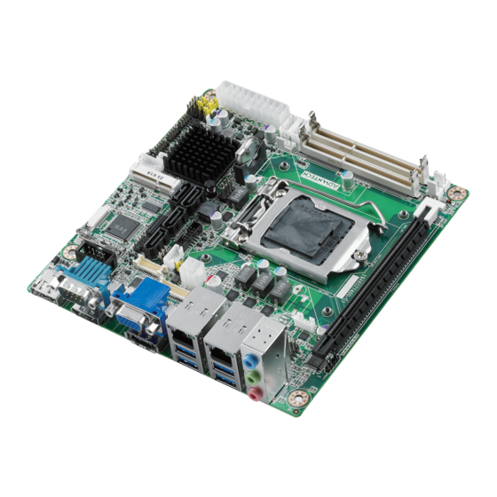
Fortec Star AIMB-274 User Manual (120 pages)
Intel Core i7/i5/i3/Pentium/ Celeron LGA1150 Mini-ITX with CRT/LVDS/DP/DP-HDMI, 2 COM, Dual LAN, PCIe x16
Brand:
Fortec Star
| Category:
Desktop
| Size: 3 MB
Table of Contents
Declaration of Conformity
5
Ordering Information
8
Initial Inspection
9
Table of Contents
10
Chapter 1 General Information
14
Introduction
15
Features
15
Specifications
15
System
15
Memory
15
Input/Output
15
Graphics
16
Ethernet LAN
16
Industrial Features
16
Mechanical and Environmental Specifications
16
Jumpers and Connectors
17
Board Layout: Jumper and Connector Locations
18
Table 1.2: Jumper List
18
AIMB-274 Board Diagram
19
Safety Precautions
19
Jumper Settings
20
CMOS Clear (CMOS1)
20
How to Set Jumpers
20
ME Enable/Disable Jumper (JME1)
20
(Jwdt1+Jobs1)
21
Power LED and Keyboard Lock Pin Header (JFP2)
21
Power Switch/Hdd Led/Smbus/Speaker Pin Header (JFP1)
21
Watchdog Timer Output and OBS Beep (JWDT1+JOBS1)
21
ATX/AT Mode Selection (PSON1)
22
COM1 RI# Pin RI#/5V/12V Select (JCOM1)
22
LVDS Panel Voltage Selection (JLVDS1, JLVDS2)
22
System Memory
23
Memory Installation Procedures
23
Cache Memory
23
Processor Installation
23
Chapter 2 Connecting Peripherals
26
Introduction
27
USB Ports (LAN1_USB12/LAN2_USB34/USB56/USB78/USB910)
27
VGA Connector(VGA1)
28
Serial Ports (COM1~COM2)
29
PS/2 Keyboard and Mouse Connector (KBMS1)
30
CPU Fan Connector (CPU_FAN1)
30
System FAN Connector (SYSFAN1/2)
31
Power Switch/Hdd Led/Smbus/Speaker Pin Header (JFP1) & Power LED and Keyboard Lock Pin Header (JFP2)
32
ATX Soft Power Switch (JFP1/PWR_SW)
32
Reset (JFP1/RESET)
32
Hdd Led (Jfp1/Hddled)
32
External Speaker (JFP1/SPEAKER)
32
Power LED and Keyboard Lock Connector
33
Lock)
33
Display Port and HDMI Common Connector (DP-HDMI1)
33
Display Port Connector (DP2)
34
SATA Signal Connector (SATA1 ~ SATA4) & External SATA/USB 2.0 Combo Connector (ESATA1)
35
Sata_Pwr1/2
35
HD Analog Audio Interface (AUDIO1, FPAUD1)
36
PCI-E X16 Slot (PCIEX16_1)
37
LVDS Panel Connector (LVDS1)
37
LVDS Backlight Inverter Power Connector (INV1)
38
Embedded Display Port Connector (EDP1), BOM Optional
39
MINIPCIE and Msata Connector (MINIPCIE1)
39
MINIPCIE Connector (MINIPCIE2) & SIM Card Socket (SIM1)
40
HD Digital Audio Interface (SPDIF1)
40
Audio Amplifier Output Connector (AMP1), BOM Optional
41
General Purpose I/O Pin Header (GPIO1)
41
SPI BIOS Flash Socket (SPI1)
42
SPI Programming Pin Header (SPI_CN1)
42
Low Pin Count Header (LPC1)
43
Case-Open Detect Connector (JCASE1)
43
ATX 12V Power Supply Connector (ATX12V1) & ATX Power Supply Connector (ATXPWR1)
44
Battery Holder (BAT1)
44
CPU Socket (CPU1)
45
DDR3 SO-DIMM Socket (DIMMA1, DIMMB1)
45
BIOS Operation
46
Chapter 3 BIOS Operation
46
Introduction
47
BIOS Setup
47
Main Menu
48
Advanced BIOS Features
49
Chipset
67
Boot
81
Security
82
Save & Exit
83
Chapter 4 Software Introduction & Service
84
Introduction
85
Value-Added Software Services
85
Software API
85
Software Utility
87
Chapter 5 Chipset Software Installation Utility
88
Before You Begin
89
Introduction
89
Windows 7/8 Driver Setup
90
Chapter 6 VGA Setup
92
Introduction
93
Windows 7/8
93
Chapter 7 LAN Configuration
94
Introduction
95
Features
95
Installation
95
Windows® 7/8 Driver Setup (Intel I217LM / I211AT)
96
Appendix A I/O Pin Assignments
98
SATA Signal Connector (SATA1~SATA4)
99
External SATA/USB 2.0 Combo Connector (ESATA1)
99
SATA Power Connector (SATA_PWR1, SATA_PWR2)
100
MINIPCIE and Msata Connector (MINIPCIE1)
100
A.3 SATA Power Connector (SATA_PWR1, SATA_PWR2)
100
Table A.5: Msata Connector (MINIPCIE1)
101
MINIPCIE Connector (MINIPCIE2)
102
SIM Card Socket (SIM1)
103
Display Port and HDMI Common Connector (DP-HDMI1)
104
Hdmi1)
104
Display Port Connector (DP2)
105
VGA Connector (VGA1)
105
LVDS Panel Connector (LVDS1)
106
LVDS Backlight Inverter Power Connector (INV1)
107
Embedded Display Port Connector (EDP1)
107
USB Header (USB56,USB78, USB910)
108
RJ45+USB 3.0 Stack Connector (LAN1_USB12, LAN2_USB34)
108
CI-E X16 Slot (PCIEX16_1)
109
Table A.16:USB
109
HD Digital Audio Interface (SPDIF1)
111
HD Analog Audio Interface (AUDIO1, FPAUD1)
112
Table A.18:HD Digital Audio Interface (SPDIF1)
112
Audio Amplifier Output Connector (AMP1)
113
General Purpose I/O Pin Header (GPIO1)
113
SPI BIOS Flash Socket (SPI1)
113
SPI Programming Pin Header (SPI_CN1)
114
Low Pin Count Header (LPC1)
114
Table A.23:SPI BIOS Flash Socket (SPI1)
114
SMBUS Programming I/F for Vcore Controller (JSMB1)
115
Case-Open Detect Connector (JCASE1)
115
PS/2 Keyboard and Mouse Connector (KBMS1)
115
COM Port (COM1, COM2)
116
CPU FAN Power Connector (CPUFAN1)
117
SYSTEM FAN Power Connector (SYSFAN1, SYSFAN2)
117
Sysfan2)
117
ATX 12V Power Supply Connector (ATX12V1)
117
ATX Power Supply Connector(ATXPWR1)
118
Advertisement
Advertisement
Related Products
Fortec Star Advantech AIMB-586
Fortec Star AIMB586QG2-00A1E
Fortec Star AIMB586WG2-00A1E
Fortec Star AIMB-586L00A1E
Fortec Star ADVANTECH AIMB-229
Fortec Star ASUS IoT
Fortec Star ASUS IoT PE800G
Fortec Star Categories
Receiver
Monitor
Motherboard
Single board computers
Set-top boxes
More Fortec Star Manuals
Login
Sign In
OR
Sign in with Facebook
Sign in with Google
Upload manual
Upload from disk
Upload from URL