Table of Contents
Advertisement
Our company network supports you worldwide with offices in Germany, Austria,
Switzerland, Great Britain and the USA. For more information please contact:
FORTEC Elektronik AG
Hauptniederlassung
Lechwiesenstr. 9
86899 Landsberg am Lech
Telefon:
+49 (0) 8191 91172-0
Telefax:
+49 (0) 8191 21770
E-Mail:
sales@fortecag.de
Internet:
www.fortecag.de
FORTEC Elektronik AG
Büro Wien
Nuschinggasse 12
A-1230 Wien
Telefon:
+43 1 8673492-0
Telefax:
+43 1 8673492-26
E-Mail:
office@fortec.at
Internet:
www.fortec.at
The information contained in this document has been carefully researched and is, to the best
of our knowledge, accurate. However, we assume no liability for any product failures or
damages, immediate or consequential, resulting from the use of the information provided
herein. Our products are not intended for use in systems in which failures of product could
result in personal injury. All trademarks mentioned herein are property of their respective
owners. All specifications are subject to change without notice.
Manual
AIMB-274
Advantech
FORTEC Elektronik AG
Büro West
Hohenstaufenring 55
50674 Köln
Telefon:
Telefax:
E-Mail:
Internet:
ALTRAC AG
(Tochter der FORTEC):
Bahnhofstraße 3
CH-5436 Würenlos
Telefon:
Telefax:
E-Mail:
Internet:
+49 (0) 221 272 273-0
+49 (0) 221 272 273-10
west@fortecag.de
www.fortecag.de
+41 (0) 44 7446111
+41 (0) 44 7446161
info@altrac.ch
www.altrac.ch
Advertisement
Table of Contents

Subscribe to Our Youtube Channel
Related Manuals for Fortec Star AIMB-274

Summary of Contents for Fortec Star AIMB-274
- Page 1 Manual AIMB-274 Advantech Our company network supports you worldwide with offices in Germany, Austria, Switzerland, Great Britain and the USA. For more information please contact: FORTEC Elektronik AG FORTEC Elektronik AG Hauptniederlassung Büro West Lechwiesenstr. 9 Hohenstaufenring 55 86899 Landsberg am Lech 50674 Köln...
- Page 2 User Manual AIMB-274 Intel® Core™ i7/i5/i3/Pentium/ Celeron LGA1150 Mini-ITX with CRT/LVDS/DP/DP-HDMI, 2 COM, Dual LAN, PCIe x16...
- Page 3 Intel® Core™ i7/i5/i3, Pentium, Celeron® is trademark of Intel Corporation WinBond is a trademark of Winbond Corporation. All other product names or trademarks are properties of their respective owners. Part No. 2006027400 Edition 1 Printed in China August 2013 AIMB-274 User Manual...
- Page 4 In addition, free technical support is available from Advantech engineers every busi- ness day. We are always ready to give advice on application requirements or specific information on the installation and operation of any of our products. AIMB-274 User Manual...
-
Page 5: Declaration Of Conformity
Discard used batteries according to the manufacturer's instructions. CPU Compatibility CPU Family Speed L3 cache QS QE75 I5-4670S 3.1GHz QS QE73 I7-4770S 3.1G 3.1GHz QE74 I5-4570S 2.9G 2.9GHz I5-4570TE 2.7GHz E3-1268L (QEEG) V3 2.3GHz I3-4330 (QDMX) 3.5GHz Pentium G3420 (QDN1) 3.2GHz AIMB-274 User Manual... - Page 6 78.B2GC9.AF Apacer H5TQ2G83BFR PASS 1333 DDR3 (256x8) DDR3 SODIMM 78.B2GC9.42 ELPIDA Apacer PASS 1333 DDR3 J2108BCSE-DJ-F ELPIDA DDR3 SODIMM 78.B2GC9.42 Apacer J2108ECSE-DJ-F PASS 1333 DDR3 256x8 ELPIDA DDR3 SODIMM 78.C2GCM.4 Apacer J4208BASE-DJ-F PASS 1333 DDR3 230C 512x8 AIMB-274 User Manual...
- Page 7 DDR3 D9PFJ DDR3 SODIMM TS1GSK64V6 MICRON IZD27 Transcend PASS 1600 DDR3 D9PBC 79T5 512x8 DDR3 SODIMM TS1GSK64W SEC 231 HYK0 Transcend PASS 1600 DDR3 K4B4G0846B DDR3 SODIMM AW24M64F8 SEC 140 HYK0 PASS 1600 DDR3 BLK0S K4B4G0846B 512x8 AIMB-274 User Manual...
-
Page 8: Ordering Information
A product returned without proof of the purchase date is not eligible for warranty service. Write the RMA number visibly on the outside of the package and ship it prepaid to your dealer. AIMB-274 User Manual... -
Page 9: Initial Inspection
It should be free of marks and scratches and in perfect working order upon receipt. As you unpack the aimb-274, check it for signs of ship- ping damage. (For example, damaged box, scratches, dents, etc.) If it is damaged or it fails to meet the specifications, notify our service department or your local sales representative immediately. -
Page 10: Table Of Contents
Table 1.2: Jumper List ..............5 Board layout: Jumper and Connector Locations ........5 Figure 1.1 Jumper and Connector Location ........ 5 AIMB-274 Board Diagram ................. 6 Figure 1.2 AIMB-274 Board Diagram .......... 6 Safety Precautions ..................6 Jumper Settings ..................7 1.8.1 How to Set Jumpers.............. - Page 11 Software Introduction & Service ..71 Introduction ..................... 72 Value-Added Software Services ............. 72 4.2.1 Software API................72 4.2.2 Software Utility................74 Chapter Chipset Software Installation Utility Before You Begin..................76 Introduction ..................... 76 Windows 7/8 Driver Setup ..............77 AIMB-274 User Manual...
- Page 12 Table A.19:AUDIO1 ..............99 Table A.20:FPAUD1 ..............99 A.18 Audio Amplifier Output Connector (AMP1) ........... 100 Table A.21:Audio Amplifier Output Connector (AMP1)..... 100 A.19 General Purpose I/O Pin Header (GPIO1)..........100 Table A.22:General Purpose I/O Pin Header (GPIO1) ..... 100 AIMB-274 User Manual...
- Page 13 Table A.32:SYSTEM FAN Power Connector (SYSFAN1, SYSFAN2).............. 104 A.29 ATX 12V Power Supply Connector (ATX12V1) ........104 Table A.33:ATX 12V Power Supply Connector (ATX12V1) ..104 A.30 ATX Power Supply Connector(ATXPWR1) .......... 105 Table A.34:ATX Power Supply Connector(ATXPWR1).... 105 AIMB-274 User Manual...
-
Page 14: Chapter 1 General Information
Chapter General Information... -
Page 15: Introduction
Introduction AIMB-274 is designed with the Intel® Q87 for industrial applications that require both performance computing and enhanced power management capabilities. The mother- board supports Intel desktop Core i7-4770S 3.1GHz / Core i7-4770TE 2.3GHz / i5- 4570S 2.9GHz / i5-4570TE 2.7GHz / i3-4330 3.5GHz / i3-4330TE 2.4GHz / Pentium G3420 3.2GHz/ Pentium G3320TE 2.3GHz / Xeon E3-1268L V3 2.3GHz processor... -
Page 16: Graphics
1.69A, +3.3V @ 0.87A, +12V @ 3.71A, 5VSB @ 0.52A Measure the maximum current value which system under maximum load (CPU: Top speed, RAM & Graphic: Full loading) Board size: 170 mm x 170 mm (6.69" x 6.69") Board weight: 0.365 kg AIMB-274 User Manual... -
Page 17: Jumpers And Connectors
Jumpers and Connectors Connectors on the AIMB-274 motherboard link it to devices such as hard disk drives and a keyboard. In addition, the board has a number of jumpers used to configure your system for your application. The tables below list the function of each of the board jumpers and connectors. Later sections in this chapter give instructions on setting jumpers. -
Page 18: Board Layout: Jumper And Connector Locations
Power LED and Keyboard Lock Pin Header JWDT1+JOBS1 Watchdog Timer Output and OBS Beep PSON1 ATX/AT Mode Selection JLVDS1, JLVDS2 LVDS Panel Voltage Selection JCOM1 COM1 RI# pin RI#/5V/12V Select Board layout: Jumper and Connector Locations Figure 1.1 Jumper and Connector Location AIMB-274 User Manual... -
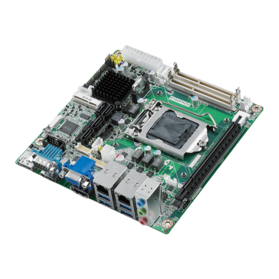
Page 19: Aimb-274 Board Diagram
AIMB-274 Board Diagram Figure 1.2 AIMB-274 Board Diagram Safety Precautions Warning! Always completely disconnect the power cord from chassis whenever you work with the hardware. Do not make connections while the power is on. Sensitive electronic components can be damaged by sudden power surges. -
Page 20: Jumper Settings
1.8.2 CMOS Clear (CMOS1) The AIMB-274 motherboard contains a jumper that can erase CMOS data and reset the system BIOS information. Normally this jumper should be set with pins 1-2 closed. If you want to reset the CMOS data, set CMOS1 to 2-3 closed for just a few seconds, and then move the jumper back to 1-2 closed. -
Page 21: Power Switch/Hdd Led/Smbus/Speaker Pin Header (Jfp1)
Signal LED Power Keyboard LOCK# 1.8.6 Watchdog Timer Output and OBS Beep (JWDT1+JOBS1) Table 1.7: Watchdog Timer Output and OBS Beep (JWDT1+JOBS1) Function Jumper Setting Watchdog Timer Output(2-3) (Default) OBS BEEP(4-5) (Default) (2 and 3)+(4 and 5) AIMB-274 User Manual... -
Page 22: Atx/At Mode Selection (Pson1)
Jumper position for 3.3V (Default) JLVDS1.1 and JLVDS1.2 Jumper position for 12V JLVDS1.2 and JLVDS2.2 1.8.9 COM1 RI# Pin RI#/5V/12V Select (JCOM1) Table 1.10: COM1 RI# Pin RI#/5V/12V Select (JCOM1) Function Jumper Setting Jumper position for RI#(Default) 1 and 2 AIMB-274 User Manual... -
Page 23: System Memory
5 and 6 System Memory AIMB-274 has two sockets for a 204-pin DDR3 SODIMM. This socket uses a 1.5 V unbuffered double data rate synchronous DRAM (DDR SDRAM). DRAM is available in capacities of 1 GB, 2 GB, 4 GB and 8 GB. The sockets can be filled in any combi- nation with SODIMMs of any size, giving a total memory size between 1 GB, 2 GB, 4 GB, 8 GB and 16 GB. - Page 24 Chapter 1 General Information...
- Page 25 AIMB-274 User Manual...
-
Page 26: Chapter 2 Connecting Peripherals
Chapter Connecting Peripherals... -
Page 27: Introduction
USB Ports (LAN1_USB12/LAN2_USB34/USB56/ USB78/USB910) The AIMB-274 provides up to ten USB ports. Four USB3.0 on the rear side and six pin header on the board. The USB interface complies with USB Specification Rev. 2.0 and Rev. 3.0 supporting transmission rates up to 625 Mbps and is fuse protected. -
Page 28: Vga Connector(Vga1)
VGA Connector(VGA1) The AIMB-274 includes VGA interface that can drive conventional VGA displays. VGA1 is a standard 15-pin D-SUB connector commonly used for VGA. AIMB-274 User Manual... -
Page 29: Serial Ports (Com1~Com2)
Serial Ports (COM1~COM2) COM1 COM2 AIMB-274 supports two serial ports, COM1 supports RS-232 function, COM2 sup- ports RS-232/422/485 function by BIOS selection. These ports can connect to serial devices, such as a mouse or a printer, or to a com- munications network. -
Page 30: Ps/2 Keyboard And Mouse Connector (Kbms1)
PS/2 Keyboard and Mouse Connector (KBMS1) On board 6-pin wafer box connector, supports one standard PS/2 keyboard, one standard PS/2 mouse. CPU Fan Connector (CPU_FAN1) If a fan is used, this connector supports cooling fans of 500 mA (6 W) or less. AIMB-274 User Manual... -
Page 31: System Fan Connector (Sysfan1/2)
System FAN Connector (SYSFAN1/2) If a fan is used, this connector supports cooling fans of 500 mA (6 W) or less. AIMB-274 User Manual... -
Page 32: Power Switch/Hdd Led/Smbus/Speaker Pin Header (Jfp1) & Power Led And Keyboard Lock Pin Header (Jfp2)
External speaker (JFP1/SPEAKER) JFP1/SPEAKER is a 4-pin connector for an external speaker. If there is no external speaker, the AIMB-274 provides an onboard buzzer as an alternative. To enable the buzzer, set pins 7 & 10 as closed. AIMB-274 User Manual... -
Page 33: Power Led And Keyboard Lock Connector
(on back plane) pins 2-3 closed pins 1-2 closed panel switch via cable jumper setting System On System Suspend Fast flashes Fast flashes Fast flashes System Off Slow flashes Display Port and HDMI Common Connector (DP- HDMI1) AIMB-274 User Manual... -
Page 34: Display Port Connector (Dp2)
Note! NOTE: When using HDMI cable in the dual DisplayPort/HMI connector, make sure to plug in the HDMI connector "to the right side", to prevent wrong placement. 2.10 Display Port Connector (DP2) AIMB-274 User Manual... -
Page 35: Sata Signal Connector (Sata1 ~ Sata4) & External Sata/Usb 2.0 Combo Connector (Esata1)
SATA Signal Connector (SATA1 ~ SATA4) & External SATA/USB 2.0 Combo Connector (ESATA1) SATA1~SATA4 ESATA1 AIMB-274 features a high performance Serial ATA III interface (up to 600 MB/s) which eases hard drive cabling with thin, space-saving cables. 2.12 SATA_PWR1/2 AIMB-274 User Manual... -
Page 36: Hd Analog Audio Interface (Audio1, Fpaud1)
Connect this connector with the front panel audio I/O module cable. AUDIO1 FPAUD1 Note! For motherboards with the optional HD Audio feature, we recommend that you connect a high-definition front panel audio module to this con- nector to take advantage of the motherboard’s high definition audio capability. AIMB-274 User Manual... -
Page 37: Pci-E X16 Slot (Pciex16_1)
2.14 PCI-E x16 Slot (PCIEX16_1) AIMB-274 provides 1 x PCI express x16 slot. 2.15 LVDS Panel Connector (LVDS1) The SPI flash card pin header may be used to flash BIOS if the AIMB-274 cannot power on. AIMB-274 User Manual... -
Page 38: Lvds Backlight Inverter Power Connector (Inv1)
2.16 LVDS Backlight Inverter Power Connector (INV1) Note! Signal Description Signal Signal Description Vadj=0.75 V (Recommended: 4.7 KΩ, >1/16 W) ENBKL LCD backlight ON/OFF control signal AIMB-274 User Manual... -
Page 39: Embedded Display Port Connector (Edp1), Bom Optional
2.17 Embedded Display Port Connector (EDP1), BOM optional 2.18 MINIPCIE and mSATA Connector (MINIPCIE1) AIMB-274 User Manual... -
Page 40: Minipcie Connector (Minipcie2) & Sim Card Socket (Sim1)
2.19 MINIPCIE Connector (MINIPCIE2) & SIM Card Socket (SIM1) SIM1 2.20 HD Digital Audio Interface (SPDIF1) AIMB-274 User Manual... -
Page 41: Audio Amplifier Output Connector (Amp1), Bom Optional
2.21 Audio Amplifier Output Connector (AMP1), BOM optional 2.22 General Purpose I/O Pin Header (GPIO1) AIMB-274 User Manual... -
Page 42: Spi Bios Flash Socket (Spi1)
2.23 SPI BIOS Flash Socket (SPI1) The SPI flash card pin header may be used to flash BIOS if the AIMB-274 cannot power on. 2.24 SPI Programming Pin Header (SPI_CN1) AIMB-274 User Manual... -
Page 43: Low Pin Count Header (Lpc1)
2.25 Low Pin Count Header (LPC1) 2.26 Case-Open Detect Connector (JCASE1) AIMB-274 User Manual... -
Page 44: Atx 12V Power Supply Connector (Atx12V1) & Atx Power Supply Connector (Atxpwr1)
2.27 ATX 12V Power Supply Connector (ATX12V1) & ATX Power Supply Connector (ATXPWR1) 2.28 Battery Holder (BAT1) AIMB-274 User Manual... -
Page 45: Cpu Socket (Cpu1)
2.29 CPU Socket (CPU1) 2.30 DDR3 SO-DIMM Socket (DIMMA1, DIMMB1) AIMB-274 User Manual... -
Page 46: Bios Operation
Chapter BIOS Operation... -
Page 47: Introduction
AIMB-274 setup screens. BIOS Setup The AIMB-274 Series system has AMI BIOS built in, with a CMOS SETUP utility that allows users to configure required settings or to activate certain system features. The CMOS SETUP saves the configuration in the CMOS RAM of the motherboard. -
Page 48: Main Menu
Date using the <Arrow> keys. Enter new values through the keyboard. Press the <Tab> key or the <Arrow> keys to move between fields. The date must be entered in MM/DD/YY format. The time must be entered in HH:MM:SS format. AIMB-274 User Manual... -
Page 49: Advanced Bios Features
3.2.2 Advanced BIOS Features Select the Advanced tab from the AIMB-274 setup screen to enter the Advanced BIOS Setup screen. You can select any of the items in the left frame of the screen, such as CPU Configuration, to go to the sub menu for that item. You can display an Advanced BIOS Setup option by highlighting it using the <Arrow>... - Page 50 PCI Latency Timer Value to be programed into PCI Latency Timer Register. VGA Palette Snoop Enable or Disable VGA palette registers snooping. PERR# Generation Enable or Disable PERR# Generation. SERR#Generation Enable or Disable SERR# Generation. AIMB-274 User Manual...
- Page 51 Defines number of retry attempts software will take to retrain the link if previous training attempt was unsuccessful. Link Training Timeout Defines number of micro-seconds software that will wait before polling "Link Training " bit in link status register. Values range from 10 to 1000 uS. Unpopulated Links AIMB-274 User Manual...
- Page 52 This item allows users to enable or disable hibernation ACPI Sleep state This item allows users to set the ACPI sleep state Lock Legacy Resources This item allows users to lock legacy devices’ resources. S3 Video Repost Enable or disable video repost AIMB-274 User Manual...
- Page 53 3.2.2.3 Trusted Computing Security Device Support Enable or disable BIOS support for security device. AIMB-274 User Manual...
- Page 54 3.2.2.4 S5 RTC wake Settings Wake system with fixed time Enable or disable system wake on alarm event AIMB-274 User Manual...
- Page 55 3.2.2.5 CPU Configuration 3.2.2.6 SATA Configuration AIMB-274 User Manual...
- Page 56 Port 4 Enable or disable SATA Port 4. Hot Plug Enable or disable hot plug function. SATA Device Type Select the type for SATA device. Spin Up Device Enable or disable Spin up device. AIMB-274 User Manual...
- Page 57 IRRT Only on eSATA Enable or disable IRRT Only on eSATA. Smart Response Technology Enable or disable Smart Response Technology. OROM UI delay This item allows users to choose the delay time for option ROM. AIMB-274 User Manual...
- Page 58 3.2.2.8 INTEL Rapid Star Technology Intel® Rapid start technology This item allows users to enable or disable Intel rapid start technology. AIMB-274 User Manual...
- Page 59 3.2.2.9 PCH(FW) Configuration PCH-FW Version PCH-FW page shows Intel ME FW information. MDES BIOS Status Code Enable or disable MDES BIOS Status Code. AIMB-274 User Manual...
- Page 60 Me FW Image Re-Flash This item allows users to enable or disable Me FW image re-flash function. 3.2.2.10 Intel® Anti-Theft Technology Configuration AIMB-274 User Manual...
- Page 61 This item allows users to enable or disable MEBx debug message. Un-Configure ME This item allows users to un-configure ME without password. Amt Wait Timer Set timer to wait before sending ASF_GET_BOOT_OPTIONS. Disable ME This item allows users to enable or disable ME function. AIMB-274 User Manual...
- Page 62 USB configuration Legacy USB support Enables support for legacy USB. Auto option disables legacy support if no USB devices are connected. USB3.0 support This item allows users to enable or disable USB3.0 function. XHCI Hand-off AIMB-274 User Manual...
- Page 63 This item allows users to set backlight enable polarity. Case open This item allows users to enable or disable case open function. Resume on Ring This item allows users to enable or disable resume on ring function. AIMB-274 User Manual...
- Page 64 3.2.2.14 Super IO Configuration AIMB-274 User Manual...
- Page 65 Interface Config Change the Serial interface. Select <RS-232> ,<RS-422> or <RS-485> inter- face. RS422/RS485 Termination resistors If serial interface is RS422 or RS485, please enable this item. 3.2.2.15 PC Health Status This Page Shows AIMB-274 PC Health. AIMB-274 User Manual...
- Page 66 3.2.2.16 Serial Port Console Redirection Console Redirection This item allows users to enable or disable console redirection. AIMB-274 User Manual...
-
Page 67: Chipset
3.2.3 Chipset This page provides information of the chipset on AIMB-274. PCH-IO Configuration AIMB-274 User Manual... - Page 68 Enable or disable PCIE to wake the system from S5. DeepSx Power Policies Enable or Disable Deep Sleep mode. Restore AC Power Loss This item allows users to select off, on and last state. 3.2.3.1 PCI Express Configuration AIMB-274 User Manual...
- Page 69 This item allows users to enable or disable PCIe-USB Glitch W/A. PCIE Root Port Function Swapping This item allows users to enable or disable PCIE Root Port Function Swapping. Subtractive Decode This item allows users to enable or disable Subtractive Decode. AIMB-274 User Manual...
- Page 70 This item allows users to enable or disable the PME SCI function. Hot Plug This item allows users to enable or disable the PCI Express hot plug function. PCIe Speed Select PCI Express port speed [Auto, Gen1, Gen2]. AIMB-274 User Manual...
- Page 71 Smart auto setting remembers the last setting, but auto mode does not. Using smart auto setting, USB devices may not be recognized when system rebooting with more than one USB device connected. BTCG Enables or disables the BTCG function. AIMB-274 User Manual...
- Page 72 3.2.3.3 PCH Azalia Configuration Azalia Control detection of the Azalia device. Disable = Azalia will be unconditionally disabled Enable=Azalia will be unconditionally enabled Auto=Azalia will be enabled if present, disabled otherwise AIMB-274 User Manual...
- Page 73 3.2.3.4 System Agent (SA) Configuration VT-d This item allows users to enable or disable VT-d. Graphic Configuration AIMB-274 User Manual...
- Page 74 Select the video device which will be activated during POST. Secondary boot display selection will appear based on customer's selection. Note! The triple display can only working PASS under Windows 7, and the 2nd and 3rd display can not work under DOS. AIMB-274 User Manual...
- Page 75 PASS DP2+EDP PASS PASS DP1+LVDS PASS PASS HDMI+LVDS PASS PASS DP2+LVDS PASS PASS VGA+DP1+DP2 PASS VGA+HDMI+DP2 PASS VGA+DP1+EDP PASS VGA+DP1+LVDS PASS VGA+HDMI+EDP PASS VGA+HDMI+LVDS PASS VGA+DP2+EDP PASS VGA+DP2+LVDS PASS DP1+DP2+LVDS PASS DP1+DP2+EDP PASS HDMI+DP2+LVDS PASS HDMI+DP2+EDP PASS AIMB-274 User Manual...
- Page 76 This item allows users to enable or disable DMI Extended Synch. DMI Gen 2 This item allows users to select DMI speed. DMI De-emphasis Control Configure the De-emphasis control on DMI. DMI IOT This item allows users to enable or disable DMI IOT. AIMB-274 User Manual...
- Page 77 Perform PEG Swing Control, on IVB C0 and Later. PEG Gen3 Equalization This item allows users to enable or disable PEG Gen3 Equalization function. Gen3 Eq Phase 2 This item allows users to enable or disable Gen3 Eq Phase 2 function. AIMB-274 User Manual...
- Page 78 This item allows users to enable or disable research Gen3 Eq Preset function. Allow PERST# GPIO Usage This item allows users to enable or disable Allow PERST# GPIO function. Lan 0 ~ 15 Root port preset value for Gen3 Equalization. AIMB-274 User Manual...
- Page 79 Lan 0 ~ 15 End point preset value for Gen3 Equalization. Lan 0 ~ 15 End point Hint value for Gen3 Equalization. AIMB-274 User Manual...
- Page 80 This item allows users to enable or disable Mc Lock function. Ch Hash Support This item allows users to enable or disable Ch Hash function. Ch Hash Mask Set the BIT(s) to be included in the XOR function. NOTE: BIT mask corre- sponds to BITS[19:6] AIMB-274 User Manual...
-
Page 81: Boot
Select the Power-on state for Numlock. Quiet Boot If this option is set to Disabled, the BIOS display normal POST messages. If Enabled, an OEM Logo is shown instead of POST messages. Boot Option Priorities Set the system boot order. AIMB-274 User Manual... -
Page 82: Security
3.2.5 Security Select Security Setup from the AIMB-274 Setup main BIOS setup menu. All Security Setup options, such as password protection and virus protection are described in this section. To access the sub menu for the following items, select the item and press<Enter>: Change Administrator / User Password. -
Page 83: Save & Exit
This item allows you to restore the user defaults to all the options. Boot Override Boot device selection can override your boot priority. Lauch EFI Shell from filesystem device Attempts to Launch EFI Shell application (Shellx64.efi) from one of the available filesystem devices. AIMB-274 User Manual... -
Page 84: Software Introduction & Service
Chapter Software Introduction & Service... -
Page 85: Introduction
1995. It is used in personal computers and serv- ers for low-speed system management communications. The SMBus API allows a developer to interface a embedded sys- tem environment and transfer serial messages using the SMBus protocols, allowing multiple simultaneous device control. AIMB-274 User Manual... - Page 86 System Throttling Refers to a series of methods for reducing power consump- tion in computers by lowering the clock frequency. This API allows the user to adjust the clock from 87.5% to 12.5%. AIMB-274 User Manual...
-
Page 87: Software Utility
The eSOS also provide for remote connection via Telnet server and FTP server so the administrator can attempt to rescue the system. Note: This function requires BIOS cus- tomization. AIMB-274 User Manual... -
Page 88: Chipset Software Installation Utility
Chapter Chipset Software Installation Utility... -
Page 89: Before You Begin
To facilitate the installation of the enhanced display drivers and utility software, read the instructions in this chapter carefully. The drivers for the AIMB-274 are located on the software installation CD. The driver in the folder of the driver CD will guide and link you to the utilities and drivers under a Windows system. -
Page 90: Windows 7/8 Driver Setup
Windows 7/8 Driver Setup Insert the driver CD into your system's CD-ROM drive. You can see the driver folder items. Navigate to the "Intel Chip" folder and click "infinst_autol.exe" to complete the installation of the driver. AIMB-274 User Manual... - Page 91 AIMB-274 User Manual...
-
Page 92: Chapter 6 Vga Setup
Chapter VGA Setup... -
Page 93: Introduction
Insert the driver CD into your system's CD-ROM drive. You can see the driver folders items. Navigate to the "Intel Graphics" folder and click "setup.exe" to complete the installation of the drivers for Windows 7 and Windows 8. AIMB-274 User Manual... -
Page 94: Chapter 7 Lan Configuration
Chapter LAN Configuration... -
Page 95: Introduction
Introduction The AIMB-274 has dual Gigabit Ethernet LANs via dedicated PCI Express x1 lanes (Intel I217LM (LAN1) and I211AT (LAN2)) that offer bandwidth of up to 500 MB/sec, eliminating the bottleneck of network data flow and incorporating Gigabit Ethernet at 1000 Mbps. -
Page 96: Windows® 7/8 Driver Setup (Intel I217Lm / I211At)
Windows® 7/8 Driver Setup (Intel I217LM / I211AT) Insert the driver CD into your system's CD-ROM drive. Select the “Intel LAN” folder then navigate to the directory for your OS. AIMB-274 User Manual... - Page 97 AIMB-274 User Manual...
-
Page 98: Appendix A I/O Pin Assignments
Appendix I/O Pin Assignments... -
Page 99: Sata Signal Connector (Sata1~Sata4)
SATA Signal Connector (SATA1~SATA4) Table A.1: SATA connector (SATA1~SATA4) Signal External SATA/USB 2.0 Combo Connector (ESATA1) Table A.2: External SATA/USB 2.0 Combo Connector (ESATA1) USB Signal ESATA Signal AIMB-274 User Manual... -
Page 100: Sata Power Connector (Sata_Pwr1, Sata_Pwr2)
SATA Power Connector (SATA_PWR1, SATA_PWR2) Table A.3: SATA Power Connector (SATA_PWR1, SATA_PWR2) Signal +12V MINIPCIE and mSATA Connector (MINIPCIE1) Table A.4: MINIPCIE (MINIPCIE1) Signal Signal WAKE# +3.3Vaux Reserved Reserved +1.5V CLKREQ# Reserved Reserved REFCLK- Reserved REFCLK+ Reserved Reserved AIMB-274 User Manual... -
Page 101: Table A.5: Msata Connector (Minipcie1)
LED_WLAN# Reserved Reserved Reserved +1.5V Reserved MSATA_DETECT# +3.3Vaux Table A.5: mSATA Connector (MINIPCIE1) Signal Signal Reserved +3.3V Reserved Reserved +1.5V Reserved Reserved Reserved Reserved Reserved Reserved Reserved Reserved Reserved Reserved Reserved DETECT# Reserved +3.3V +1.5V SMB_CLK SMB_DATA AIMB-274 User Manual... -
Page 102: Minipcie Connector (Minipcie2)
Reserved Reserved Reserved +1.5V Reserved MSATA_DETECT# +3.3V MINIPCIE Connector (MINIPCIE2) Table A.6: MINIPCIE Connector (MINIPCIE2) Signal Signal WAKE# +3.3Vaux Reserved Reserved +1.5V CLKREQ# SIM_PWR SIM_DATA REFCLK- SIM_CLK REFCLK+ SIM_RESET SIM_VPP Reserved Reserved DISABLE# DETECT# RESET# PCIE_RX- +3.3Vaux AIMB-274 User Manual... -
Page 103: Sim Card Socket (Sim1)
SMB_CLK PCIE_TX- SMB_DATA PCIE_TX+ USB_D- USB_D+ +3.3Vaux +3.3Vaux Reserved V1.2_DETECT# LED_WLAN# CLINK_CLK Reserved CLINK_DATA +1.5V CLINK_RESET# Reserved +3.3Vaux SIM Card Socket (SIM1) Table A.7: SIM Card Socket (SIM1) Signal Signal UIM_PWR UIM_RESET UIM_VPP UIM_CLK UIM_DATA Reserved Reserved AIMB-274 User Manual... -
Page 104: Display Port And Hdmi Common Connector (Dp-Hdmi1)
Lane 0- TMDS Data2- Lane 1+ TMDS Data1+ Lane 1- TMDS Data1- Lane 2+ TMDS Data0+ Lane 2- TMDS Data0- Lane 3+ TMDS Clock+ Lane 3- TMDS Clock+- Reserved Reserved AUX+ AUX- DP_HPD HDMI_HPD +3.3V DP_DETECT# DP_DETECT# AIMB-274 User Manual... -
Page 105: Display Port Connector (Dp2)
Lane 0+ Lane 0- Lane 1+ Lane 1- Lane 2+ Lane 2- Lane 3+ Lane 3- DP_DETECT# AUX+ AUX- DP_HPD +3.3V VGA Connector (VGA1) Table A.10: VGA Connector (VGA1) Signal Signal GREEN BLUE Reserved Reserved HSYNC VGA_FORCE_ON VSYNC AIMB-274 User Manual... -
Page 106: Lvds Panel Connector (Lvds1)
LVDS Panel Connector (LVDS1) Table A.11: LVDS Panel Connector (LVDS1) Signal Signal LVDS_DET# OD0- ED0- OD0+ ED0+ OD1- ED1- OD1+ ED1+ OD2- ED2- OD2+ ED2+ OCK- ECK- OCK+ ECK+ DDC_CLK DDC_DAT OD3- ED3- OD3+ ED3+ LVDS_ENBKL VCON AIMB-274 User Manual... -
Page 107: Lvds Backlight Inverter Power Connector (Inv1)
BKL_EN BKL_CTRL A.12 Embedded Display Port Connector (EDP1) Table A.13: Embedded Display Port Connector (EDP1) Signal Signal Lane 0- Lane 3- Lane 0+ Lane 3+ Reserved Lane 1- Lane 1+ AUX- AUX+ Lane 2- Lane 2+ EDP_HPD AIMB-274 User Manual... -
Page 108: Usb Header (Usb56,Usb78, Usb910)
Table A.13: Embedded Display Port Connector (EDP1) A.13 USB Header (USB56,USB78, USB910) Table A.14: USB Header (USB56, USB78, USB910) Signal Signal A.14 RJ45+USB 3.0 Stack Connector (LAN1_USB12, LAN2_USB34) Table A.15: RJ45 Signal Signal MDI_0+ MDI_2+ MDI_0- MDI_2- MDI_1+ MDI_3+ MDI_1- MDI_3- AIMB-274 User Manual... -
Page 109: Ci-E X16 Slot (Pciex16_1)
CI-E x16 Slot (PCIEX16_1) Table A.17: PCI-E x 16 Slot (PCIEX16_1) Signal Signal +12V PRSNT1# +12V +12V +12V +12V SMB_CLK Reserved SMB_DATA Reserved Reserved +3.3V Reserved Reserved +3.3V +3.3VAUX +3.3V WAKE# PWRGD Reserved REFCLK+ TX0+ REFCLK- TX0- RX0+ Reserved RX0- AIMB-274 User Manual... - Page 110 RX1+ RX1- TX2+ TX2- RX2+ RX2- TX3+ TX3- RX3+ Reserved RX3- Reserved CONFIG2 TX4+ Reserved TX4- RX4+ RX4- TX5+ TX5- RX5+ RX5- TX6+ TX6- RX6+ RX6- TX7+ TX7- RX7+ Reserved RX7- TX8+ Reserved TX8- RX8+ RX8- TX9+ AIMB-274 User Manual...
-
Page 111: Hd Digital Audio Interface (Spdif1)
Table A.17: PCI-E x 16 Slot (PCIEX16_1) TX9- RX9+ RX9- TX10+ TX10- RX10+ RX10- TX11+ TX11- RX11+ RX11- TX12+ TX12- RX12+ RX12- TX13+ TX13- RX13+ RX13- TX14+ TX14- RX14+ RX14- TX15+ TX15- RX15+ Reserved RX15- Reserved A.16 HD Digital Audio Interface (SPDIF1) AIMB-274 User Manual... -
Page 112: Hd Analog Audio Interface (Audio1, Fpaud1)
HD Analog Audio Interface (AUDIO1, FPAUD1) Table A.19: AUDIO1 Signal MIC IN LINE OUT LINE IN Table A.20: FPAUD1 Signal Signal MIC IN L MIC IN R FPAUD_DETECT# LINE OUT R SENSE R1 SENSE LINE OUT L SENSE R2 AIMB-274 User Manual... -
Page 113: Audio Amplifier Output Connector (Amp1)
Table A.21: Audio Amplifier Output Connector (AMP1) Signal A.19 General Purpose I/O Pin Header (GPIO1) Table A.22: General Purpose I/O Pin Header (GPIO1) Signal Signal GPIO0 GPIO4 GPIO1 GPIO5 GPIO2 GPIO6 GPIO3 GPIO7 +3.3V A.20 SPI BIOS Flash Socket (SPI1) AIMB-274 User Manual... -
Page 114: Spi Programming Pin Header (Spi_Cn1)
SPI Programming Pin Header (SPI_CN1) Table A.24: SPI Programming Pin Header (SPI_CN1) Signal Signal +3.3V MISO MOSI A.22 Low Pin Count Header (LPC1) Table A.25: Low Pin Count Header (LPC1) Signal Signal CLK_33M RESET# FRAME# +3.3V SMB_CLK SERIRQ SMB_DATA AIMB-274 User Manual... -
Page 115: Smbus Programming I/F For Vcore Controller (Jsmb1)
Table A.26: SMBUS Programming I/F for Vcore Controller (JSMB1) Signal SMB_CLK SMB_DATA A.24 Case-Open Detect Connector (JCASE1) Table A.27: Case-Open Detect Connector (JCASE1) Signal INTRUDER# A.25 PS/2 Keyboard and Mouse Connector (KBMS1) Table A.28: PS/2 Keyboard and Mouse Connector (KBMS1) Signal KB CLK AIMB-274 User Manual... -
Page 116: Com Port (Com1, Com2)
Signal Signal DCD# DSR# RTS# CTS# DTR# COM2: Table A.30: COM Port 2 Signal Signal DCD# / 422 485 TX- 2 DSR# RXD / 422 485 TX+ RTS# TXD / 422 RX+ CTS# DTR# / 422 RX- AIMB-274 User Manual... -
Page 117: Cpu Fan Power Connector (Cpufan1)
PWM IN A.28 SYSTEM FAN Power Connector (SYSFAN1, SYSFAN2) Table A.32: SYSTEM FAN Power Connector (SYSFAN1, SYSFAN2) Signal FAN POWER DETECT A.29 ATX 12V Power Supply Connector (ATX12V1) Table A.33: ATX 12V Power Supply Connector (ATX12V1) Signal AIMB-274 User Manual... -
Page 118: Atx Power Supply Connector(Atxpwr1)
Table A.33: ATX 12V Power Supply Connector (ATX12V1) +12V +12V A.30 ATX Power Supply Connector(ATXPWR1) Table A.34: ATX Power Supply Connector(ATXPWR1) Signal Signal +3.3V +3.3V +3.3V -12V PSON# POWER_OK +5VSB +12V AIMB-274 User Manual... - Page 119 www.advantech.com Please verify specifications before quoting. This guide is intended for reference purposes only. All product specifications are subject to change without notice. No part of this publication may be reproduced in any form or by any means, electronic, photocopying, recording or otherwise, without prior written permis- sion of the publisher.
- Page 120 Our company network supports you worldwide with offices in Germany, Austria, Switzerland, Great Britain and the USA. For more information please contact: FORTEC Elektronik AG FORTEC Elektronik AG Hauptniederlassung Büro West Lechwiesenstr. 9 Hohenstaufenring 55 86899 Landsberg am Lech 50674 Köln Telefon: +49 (0) 8191 91172-0 Telefon:...
Need help?
Do you have a question about the AIMB-274 and is the answer not in the manual?
Questions and answers