Sign In
Upload
Manuals
Brands
Fluke Manuals
Thermal cameras
ThermoView TV30 Series
User Manuals: Fluke ThermoView TV30 Series Imager
Manuals and User Guides for Fluke ThermoView TV30 Series Imager. We have
1
Fluke ThermoView TV30 Series Imager manual available for free PDF download: User Manual
Fluke ThermoView TV30 Series User Manual (95 pages)
Thermal Imager Camera
Brand:
Fluke
| Category:
Thermal cameras
| Size: 2 MB
Table of Contents
Warranty
2
Table of Contents
3
List of Tables
6
List of Figures
7
Compliance Statement
9
Safety Information
10
Contacts
13
Description
14
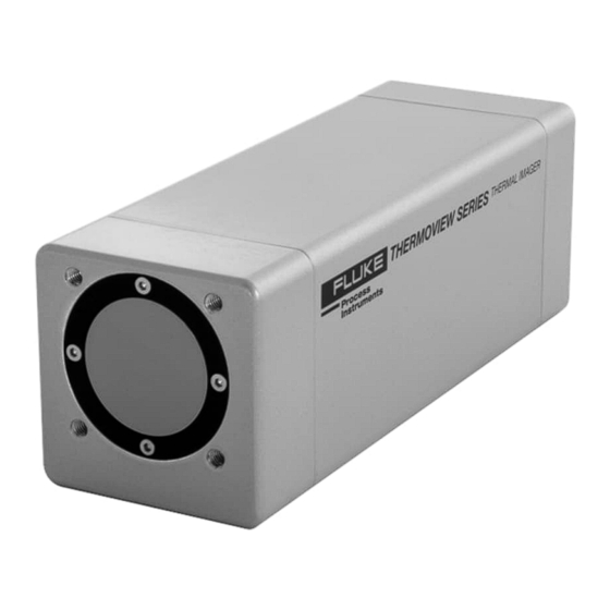
Figure 1-1: Front and Rear View of TV30 Infrared Cameras
15
Available Models
16
Figure 1-2: Available Models
16
System Architecture
17
Figure 1-3: Principal System Architecture for TV30 SA Camera
17
Technical Data
18
Measurement Specification
18
Optical Specifications
19
Standard Lens
19
Wide Angle Lens
20
Tele Lens
20
Electrical Specifications
21
Communications
22
Environmental Specifications
22
Dimensions
23
Scope of Delivery
23
Figure 2-1: Dimensions of Thermoview TV30
23
Basics
24
Measurement of Infrared Temperature
24
Emissivity of Target Object
24
Environment
25
Ambient Temperature
25
Atmospheric Quality
25
Protection
25
Electrical Interference
25
Installation
26
Positioning
26
Distance to Object
26
Focusing
26
Mounting
26
Figure 5-1: Field of View for the TV30 Camera
26
Powering
27
Power over External Supply
27
Figure 5-2: Principal Cabling of Power Supply and Ethernet
27
Power over Ethernet
28
Networking
28
Ethernet Connector
28
Figure 5-3: Principal Cabling of Power Supply and Ethernet
28
Connecting
29
12-Pin Connector
29
Figure 5-4: Connecting the Ethernet M12 Cable to the Camera
29
Figure 5-5: DIN Connector Pin Layout (Pin Side on Camera)
29
Digital Inputs
30
Digital Outputs
30
Table 5-1: Pin Assignment for DIN Connector
30
Figure 5-6: Wiring the Digital Input (Example)
30
Figure 5-7: Digital Output Using Pull-Up
31
Figure 5-8: Digital Output Using Open-Drain
31
Operation
32
Getting Started
32
LED Status Indicator
32
Figure 6-1: LED Status Indicator
32
Shutter
33
Web Server
34
Home Page
34
Figure 7-1: Home
34
Camera
35
Camera> <Values
35
Figure 7-2: Values
35
Figure 7-3: Values Selection
36
Figure 7-4: Calculated Value
37
Camera> <Conditions
38
Figure 7-5: Conditions
38
Figure 7-6: Measurement Condition
39
Figure 7-7: Combination Condition
40
Camera> <Configuration
41
Figure 7-8: Configuration
41
Settings
43
Settings> <User Management
43
Figure 7-9: Shutter Settings
43
Figure 7-10: User Management
43
Settings> <Networking
44
Figure 7-11: Networking
44
Obtain IP Address Via DHCP / Auto IP
45
Use a Static IP Address
45
HTTPS Security Certificate
45
Figure 7-12: Serial Number and Device Address
45
Settings> <Localization
46
Figure 7-13: Networking
46
Figure 7-14: Localization
46
Settings> <Device Management
47
Figure 7-15: Device Management
47
I/O
48
I/O> <Internal
48
Figure 7-16: Internal I/O
48
I/O> <External
49
Figure 7-17: WAGO Module
49
I/O> <Mqtt
51
Figure 7-18: Principle of MQTT Network Protocol
51
Figure 7-19: MQTT
51
I/O> <Opc Ua
53
Figure 7-20: Principle of OPC UA Network
53
Figure 7-21: OPC UA
53
Table 7-2: OPC UA Items
54
Accessories
56
Electrical Accessories
56
Ethernet Poe Cable (A-CB-XX-M12-W08-XX)
57
Table 8-3: Available Ethernet Poe Cables
57
Figure 8-1: Exemplary Ethernet Poe LT Cable
57
Figure 8-2: Pin Assignment (Front View)
57
12-Wire Cable, High Temp (A-CB-HT-M16-W12-XX)
58
Table 8-4: Cable Specification
58
Table 8-5: Color Assignment to DIN Connector
58
Figure 8-3: 12-Wire Cable, High Temp Version
58
12-Wire Cable, Low Temp (A-CB-LT-M16-W12-XX)
60
Table 8-6: Cable Specification
60
Table 8-7: Color Assignment to DIN Connector
60
Figure 8-4: 12-Wire Cable, Low Temp Version
60
Terminal Block (A-TV30-TB)
62
Figure 8-5: Terminal Block with Wire Color Assignment
62
Ethernet Cable (A-CB-LT-RJ45-XX)
63
Table 8-8: Ethernet Cables - Available Lengths
63
Figure 8-6: Ethernet Cable
63
Fiber Optic Cable (A-CB-FO-XXX)
64
Poe Injector (A-TV-POE1)
65
Figure 8-7: Poe Injector for Office Environments
65
Poe Injector Industrial (A-TV-POE2)
66
Power Supply DIN Rail (A-PS-DIN-24V)
67
Figure 8-8: Industrial Power Supply
67
Fiber Optic to Ethernet Converter (A-CON-FO-RJ45)
68
Ethernet Switch (A-CON-SW)
69
I/O Modules
70
Mechanical Accessories
71
Mounting Base (A-TV30-MB)
72
Figure 8-9: Mounting Base
72
Figure 8-10: Mounting Base Dimensions
72
Figure 8-11: Assembling the Mounting Base
73
Figure 8-12: Camera with Mounting Base
73
Air Purge Collar (A-TV30-AP)
74
Figure 8-13: Air Purge Collar
74
Figure 8-14: Assembling the Air Purge Collar
74
Figure 8-15: Camera with Air Purge Collar and Mounting Base
75
Water Cooling Enclosure (A-TV30-AP-WC)
76
Figure 8-16: Water Cooling Enclosure with Air Purge
76
Figure 8-17: Enclosure Connections
76
Figure 8-18: Enclosure Dimensions
77
Assembling
78
Outdoor Enclosure (A-TV-ENCVW)
80
Specification
80
Figure 8-19: Outdoor Enclosure
80
Installation
81
Figure 8-20: Dimensions
81
Swivel Bracket (A-BR-S)
85
Figure 8-21: Swivel Bracket with Mount Beam
85
Figure 8-22: Mounting Base to be Fixed to the Mount Beam of Swivel Bracket
85
Figure 8-23: Camera with Swivel Bracket
86
Protective Windows (S-TV30-PW)
87
Figure 8-24: Protective Window
87
Maintenance
88
Fail-Safe Operation
88
Troubleshooting
89
Table 9-9: Troubleshooting
89
Cleaning the Window
90
Re-Calibration
90
Appendix
91
Field of View Calculator
91
Figure 10-1: Field of View Calculator for the Camera
91
Avoidance of Condensation
92
Table 10-10: Minimum Device Temperatures [°C/°F]
92
Determination of Emissivity
93
Typical Emissivity Values
93
Advertisement
Advertisement
Related Products
Fluke ThermoView TV43
Fluke ThermoView TV46
Fluke ThermoView TV40 Series
Fluke TiR32
Fluke TiS55
Fluke TiX520
Fluke TiX885U
Fluke TiX1060
Fluke TiX1080
Fluke ThermoView Series
Fluke Categories
Measuring Instruments
Test Equipment
Multimeter
Thermometer
Laboratory Equipment
More Fluke Manuals
Login
Sign In
OR
Sign in with Facebook
Sign in with Google
Upload manual
Upload from disk
Upload from URL