Sign In
Upload
Manuals
Brands
Fluidwell Manuals
Measuring Instruments
C595-EZ
Fluidwell C595-EZ Manuals
Manuals and User Guides for Fluidwell C595-EZ. We have
1
Fluidwell C595-EZ manual available for free PDF download: Installation Manual
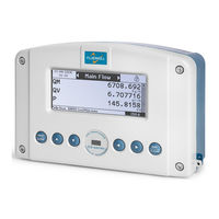
Fluidwell C595-EZ Installation Manual (56 pages)
FLOW AND ENERGY COMPUTERS FOR GAS, LIQUIDS AND STEAM
Brand:
Fluidwell
| Category:
Measuring Instruments
| Size: 2 MB
Table of Contents
Table of Contents
4
Responsibility
2
Safety Instructions
2
Disposal of Electronic Waste
2
About the Manuals
3
Warranty and Technical Support
3
Content
3
Table of Contents
4
Introduction
6
System Description of the C5-Series Product
6
Fig. 1: Generic Overview of I/O
6
Available Models
7
C561
7
C562
7
C571
7
C572
7
C581
7
C582
7
C595
7
Product Code
8
Operation
10
General Information
10
Control Panel
10
Fig. 2: Control Panel, Keys
10
Enter Main Menu
11
Navigation
11
Changing Values and Text
11
Leaving a Menu
11
Indication Measured Values of Inputs and Outputs
12
Setting the Test Current for the Analog Outputs AO1 and AO2
12
General Installation Directions
13
Explanation of the Enclosure
13
Open and Close the C5-Series
13
Open the Enclosure
13
Close the Enclosure
13
Fig. 3: Installation - Conditions
14
Extended Temperature Range: Information and Requirements
14
Installation / Surrounding Conditions
14
Fig. 4: Installation - Dimensions
16
Mechanical Installation
16
Dimensions - Enclosure
16
Mounting Instructions
17
Fig. 5: Required Space for Installation
17
Fig. 6: Installation - Position of Glands
17
Position of Entry Holes
17
Mounting Accessories
18
Fig. 7: Installation - Wall Mounting
18
Fig. 8: Installation - Pipe Mounting
18
Fig. 9: Installation - Weather Shed
18
Pressure Equalizer Vent (Breather Valve)
19
Fig. 10: Installation - Weather Shed with Pipe Mounting
19
Fig. 11: Installation - DIN Rail Mounting
19
Fig. 12: Installation - Pressure Equalization Vent
19
Electrical Safety
20
General Information
20
Electrical Installation
20
Power Supply Wiring
21
Protective Earth (PE) Connections
21
Fig. 13: Installation - Grounding Enclosure
21
Fig. 14: Installation - Grounding between Door and Body of the Enclosure
21
Loop Supply
22
Field Wiring Connections
22
Relay Outputs
22
Fig. 16: Overview - Switches and Jumpers in Back Cover
23
Configuration Switch, Lock Switch and Download Switch
23
Fig. 15: Overview - Switch in Front Cover
23
Overview Internal Contacts, Switches and Jumpers
23
Jumpers
24
Fig. 17: Jumpers Positions
24
HF Pulse Supply Selection
25
Fig. 18: HF Pulse Supply - Reference or Supply Selectors
25
Fig. 19: HF Pulse Supply - Voltage Selector
25
Fig. 21: End Resistor Switch
26
Analog Output Switches
26
Fig. 20: Analog Output Selectors
26
End Resistor Switch
26
Terminal Connector Wiring
27
Order of Installation
27
Fig. 22: Overview - Terminals
27
Overview
28
Fig. 23: Terminal Connectors - Standard and Options
28
Protective Earth
29
Terminal P1-P2: Mains Supply - Type PF or PM
29
Fig. 24: Terminal Connectors - Power Supply
29
Terminal R5-R8: Relay - Rel1-Rel2
30
Terminal T1-T6: Temperature Inputs AI1 and AI2
30
Fig. 25: Protection Slide
30
Fig. 26: Terminal Connections - Mechanical Relay Output
30
Fig. 29: Terminal Connections - Temperature Inputs: Analog (4..20 Ma) (Passive C5
31
Fig. 28: Terminal Connections - Temperature Inputs: Analog (4..20 Ma) (Active C5
31
Fig. 27: Terminal Connections - Temperature Inputs: Pt100 or Pt500 Sensors
31
Terminal T8-T9 and E1-E6; Analog Inputs AI3,AI4, AI5, AI6
32
Fig. 30: Terminal Connections -Analog Inputs (4..20 Ma) (Active C5
32
Terminal C1-C6: Communication - RS232/RS485
33
Fig. 31: Terminal Connections -Analog Inputs (4..20 Ma) (Passive C5
33
Fig. 34: COM 2 - RS485 Communication Port (Option CH2)
34
Fig. 33: COM 2 - RS232 Communication Port (Option CB)
34
Fig. 32: COM 1 - RS485 Communication Port
34
Terminal S1-S6; HF (Pulse/Frequency) Inputs HF1-HF2
34
Fig. 35: Terminal Connections - Coil Signal Input
35
Fig. 36: Terminal Connections - NPN Signal Input
35
Fig. 37: Terminal Connections - PNP Signal Input
36
Fig. 38: Terminal Connections - Reed-Switch Signal Input
36
Fig. 39: Terminal Connections - NAMUR Signal Input
37
Fig. 40: Terminal Connections - Active Signal Input
37
Fig. 42: Terminal Connections - Digital Outputs
38
Fig. 41: Terminal Connections - Digital Inputs
38
5.3.12 Terminal A1-A4: Analog Output 4-20Ma - Ao1-Ao2
38
5.3.11 Terminal R1-R4: Digital Output - Do1-Do2
38
5.3.10 Terminal S7-S8: Digital Input - Di3-Di4
38
Sealing (External, Internal)
39
Fig. 43: Terminal Connections - Settings for Analog Outputs (Passive C5)
39
Fig. 44: Terminal Connections - Settings for Analog Outputs (Active C5)
39
Fig. 45: Sealing - Wired Sealing between the Enclosure Parts
39
Fig. 46: Positioning of User Security Labels
40
Battery Replacement
41
General Directions
41
Instructions for Repair
41
Maintenance
41
Open and Close the Battery Cover
42
Replace the Battery
42
Fig. 47: Opening the Battery Cover
42
Fig. 48: Replacing the Battery
42
Fig. 49: Labels - Main Label at the Outside of the Enclosure
43
Optional External Label (-ZS)
43
External Labels
43
Main Label on Top of the Enclosure
43
Label Information
43
General Remarks Regarding the Shown Labels
43
Internal Labels
44
Internal Identification Label
44
Terminal Explanation Label
44
Fig. 50: Labels - Optional External Label
44
Fig. 51: Labels - Internal Identification Label
44
Fig. 53: Labels - Terminal Explanation Label
45
Additional Labels
45
Fig. 52: Labels - Terminal Explanation Label
45
Appendix A. Technical Specification
46
Appendix B. Declaration of Conformity
51
Appendix C. Firmware Updates
52
Fig. 54: Firmware Upload Switch
52
Appendix D. Guidelines for Installation
53
List of Figures
55
Advertisement
Advertisement
Related Products
Fluidwell C595
Fluidwell C5 Series
Fluidwell C571
Fluidwell C581
Fluidwell C582
Fluidwell C561-EL
Fluidwell C562-EL
Fluidwell C581-ES
Fluidwell C582-ES
Fluidwell C581-P
Fluidwell Categories
Measuring Instruments
Controller
Monitor
Touch Panel
Desktop
More Fluidwell Manuals
Login
Sign In
OR
Sign in with Facebook
Sign in with Google
Upload manual
Upload from disk
Upload from URL