Sign In
Upload
Manuals
Brands
Flowserve Manuals
Control Unit
B320-70
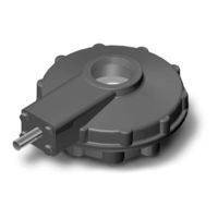
Flowserve B320-70 Actuator Gear Manuals
Manuals and User Guides for Flowserve B320-70 Actuator Gear. We have
1
Flowserve B320-70 Actuator Gear manual available for free PDF download: User Instructions
Flowserve B320-70 User Instructions (32 pages)
Brand:
Flowserve
| Category:
Control Unit
| Size: 0 MB
Table of Contents
Table of Contents
3
1 Introduction
5
Purpose
5
User Safety
5
2 Product Capabilities and Features
6
Initial Inspection and Storage Instructions
6
Product Identification
7
Inspection and Recording
7
Figure 2.1 - B320 Bevel Gear Operator
7
Storage Procedure
8
Figure 2.2 - B320 Nameplate
8
3 Operator Weights
9
Table 3.1 - Operator Weights
9
4 Installation Instructions
10
Safety Precautions
10
Safety Practices
11
Installation
11
Installing an Operator with a Threaded Stem Nut
11
Installing an Operator with a Blank Stem Nut (B320-10 through -90, One-Piece)
11
Installing an Operator with a Blank Stem Nut (B320-90, Two-Piece)
12
5 Lubrication
13
Lubrication Inspection
13
Factory Lubricant
13
Minimum Lubricant Qualities Required
14
Table 5.1 - Lubricant Quantities
14
6 Disassembly and Reassembly
15
Table 6.1 - Quantity of Ball Bearings
15
Disassembly and Reassembly of B320-10 through -80
16
Disassembly
16
Reassembly
16
Figure 6.1 - B320-10 and 20 Parts Diagram
17
Figure 6.2 - B320-30 and -40 Parts Diagram
17
Figure 6.3 - B320-50 and -70 Parts Diagram
18
Figure 6.4 - B320-80 Parts Diagram
18
Table 6.2- Common Parts List
19
Disassembly and Reassembly of B320-90
20
Disassembly
20
Reassembly
20
Figure 6.5 - B320-90 Parts Diagram
20
Disassembly and Reassembly of Spur Gear Attachments
21
Disassembly of 3:1 Spur Gear Attachment for B320-10 through -40
21
Table 6.3 - B320-90 Parts List
21
Reassembly of 3:1 Spur Gear Attachment for B320-10 through -40
22
Figure 6.6 - 3:1 SGA Parts Diagram for B320-10 through -40
22
Disassembly of 6.3:1, 10.3:1, and 10.8:1 Spur Gear Attachments for B320-50, -70, and -80
23
Reassembly of 6.3:1, 10.3:1, and 10.8:1 Spur Gear Attachments for B320-50, -70, and -80
23
Table 6.4 - 3:1 SGA Parts List for B320-10 through -40
23
Figure 6.7 - 6.3:1, 10.3:1, and 10.8:1 SGA Parts Diagram for B320-50 through -80
24
Table 6.5 - 6.3:1 , 10.3:1, and 10.8:1 SGA Parts List for B320-50 through
24
Disassembly of 5:1 Spur Gear Attachment for B320-90
25
Reassembly of 5:1 Spur Gear Attachment for B320-90
25
Figure 6.8 - 5:1 SGA Parts Diagram for B320-90
26
Table 6.6 - 5:1 SGA Parts List for B320-90
26
Disassembly of 17.5:1 Spur Gear Attachment for B320-90
27
Reassembly of 17.5:1 Spur Gear Attachment for B320-90
27
Figure 6.9 - 17.5:1 SGA Parts Diagram for B320-90
28
Table 6.7 - 17.5:1 SGA Parts List for B320-90
29
7 How to Order Parts
30
Advertisement
Advertisement
Related Products
Flowserve Limitorque B320 series
Flowserve B320-10
Flowserve B320-30
Flowserve B320-20
Flowserve B320-40
Flowserve B320-50
Flowserve B320-80
Flowserve B320-90
Flowserve GESTRA BB 1 Series
Flowserve GESTRA BB 11 G
Flowserve Categories
Control Unit
Controller
Water Pump
Valve Positioners
Industrial Equipment
More Flowserve Manuals
Login
Sign In
OR
Sign in with Facebook
Sign in with Google
Upload manual
Upload from disk
Upload from URL