Sign In
Upload
Manuals
Brands
Flintec Manuals
Control Unit
EM100-G
Flintec EM100-G Load Cell Unit Manuals
Manuals and User Guides for Flintec EM100-G Load Cell Unit. We have
1
Flintec EM100-G Load Cell Unit manual available for free PDF download: User Manual
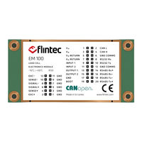
Flintec EM100-G User Manual (93 pages)
Brand:
Flintec
| Category:
Control Unit
| Size: 1.74 MB
Table of Contents
Table of Contents
2
1 EM100 Module
7
Introduction
7
Disclaimer
8
Safety Instructions
9
2 Specification
10
3 Getting Started
11
Labelling
11
Dimensions
12
Connections
13
Load-Cell Connections
14
Power Connection
15
RS-232 Connection
16
RS-485 Connection
17
Canopen Connection
18
USB Connection
18
EM100 with Adaptor Board
19
Driver Check
20
Calibration
21
Calibration Commands
21
Preparing for Calibration
21
Calibration Sequence
22
4 Commands Overview
23
5 Command Descriptions
27
System Diagnostic Commands - FPN, FFV, IS, SR, RS
27
FPN Get Device Identity
27
FFV Get Firmware Version
27
IS Get Device Status
27
SR Software Reset
28
RS Read Serial Number
28
Calibration Commands - CE, CM'n', CI, MR, DS, DP, CZ, CG, ZT, FD, IZ, ZR, ZI, TM
29
Tn, Zn, Ag, Az, Wt
29
CE Read TAC Counter/Open Calibration Sequence
29
CM 'N' Set Maximum Output Value
29
CI Set Minimum Output Value
30
MR Set Multi-Range/Multi-Interval
30
DS Set Display Step Size
31
DP Set Decimal Point Position
31
Set Calibration Zero Point
31
CG Set Calibration Gain (Span)
32
ZT Enable/Disable Zero-Tracking
32
FD Reset to Factory Default Settings
33
IZ Correction of System Zero
33
ZR Zero Range
33
ZI Initial Zero Range
34
TM Tare Mode
34
TN Set/Clear Non-Volatile Tare
35
ZN Set/Clear Non-Volatile Zero
35
AZ Absolute Zero Point Calibration (Ecal)
35
AG Absolute Gain Calibration (Ecal)
36
WT Warm-Up Time
36
Motion Detection Commands - NR, NT
37
NR Set No-Motion Range
37
NT Set No-Motion Time
37
Filter Setting Commands - FM, FL, UR
38
FM Filter Mode
38
FL Filter Setting
38
UR Update Rate & Averaging
40
Taring & Zeroing Commands - SZ, RZ, ST, RT, SP, TMV, RMV
41
SZ Set System Zero
41
RZ Reset Zero
41
ST Set Tare
42
RT Reset Tare
42
SP Set Preset Tare
42
TMV Set Tare (MV/V)
42
RMV Reset Tare (MV/V)
43
Output Commands - GG, GN, GT, GS, GMV, GW, GA, GL, OF, GH, TH, GM, RM, GO
44
Gv, Hw
44
GG Get Gross Value
44
GN Get Net Value
44
GT Get Tare Value
44
GS Get ADC Sample Value
44
GMV Get MV/V Value
44
GW Get Data String (Net, Gross & Status)
45
GA Get Triggered Average Value
46
GL Get Data String (Average, Gross & Status)
46
OF Output Format for Data String GW & GL
46
GH Get Hold Value
47
TH Trigger Hold Value
47
GM Get Peak Value
47
RM Reset Peak Value
47
GO Get Peak-To-Peak Value
48
GV Get Valley Value
48
HW Hold Weight
48
Auto-Transmit Commands - SG, SN, SX, SMV, SA, SL, SW
49
SG Send Gross Value Continuously
49
SN Send Net Value Continuously
49
SX Send ADC Sample Value Continuously
49
SMV Send MV/V Sample Value Continuously
49
SA Send Triggered Average Value Continuously
49
Send Data String Continuously (Average, Gross & Status)
50
SW Send Data String Continuously (Net, Gross & Status)
50
Commands for External I/O Control - IN, OM, IO
51
IN Read Status of Logic Inputs
51
OM Control of Logic Outputs by Host Application
51
IO Read/Modify Status of Logic Outputs
51
Set-Point Output Commands - S'n', H'n', A'n', HT
53
S'n' Set-Point Value
53
H'n' Hysteresis & Switching Action for Set-Point
53
A'n' Source Allocation for Set-Point
54
HT Hold-Time for All Set-Points
54
Communication Setup Commands - AD, NA, NS, BR, DX, CL, OP, TD, CTR, STR, SBR
55
AD Device Address - Serial Channel
55
NA Network Address - Canopen
55
NS Network Settings - Canopen
55
BR Baud-Rate - Serial Channel
56
DX Full-Duplex - Serial Channel
56
CL Close Device Address 'N
56
OP Open Device
56
TD Transmission Delay
57
CTR Set CAN Bus Termination Resistance
57
STR Set RS-485 Termination Resistance
57
SBR Set RS-485 Biasing Resistance
57
Save Calibration & Setup Data Commands - CS, WP, SS, SDD
58
CS Save Calibration Data
58
WP Save Setup Parameters
58
SS Save Set-Point Parameters
58
SDD Save Dosing Setup Parameters
59
Trigger Commands - SD, MT, TE, TR, TL
60
SD Start Delay Time
60
MT Measuring Time
60
TE Trigger Edge
60
TR Software Trigger
61
TL Trigger Level
61
Filling Commands - DI, SC, AC, GD, DT, PD1 to PD21, TR
62
DI Filling Status
65
SC Start Cycle
65
AC Abort Cycle
65
GD Get Last Dosed Weight
66
DT Get Last Tare Weight
66
PD1 Pre-Fill Mode
66
PD2 In-Flight Correction
66
PD3 Average Time Zero Check Load-Cell
66
PD4 Delay Time Tare Average
67
PD5 Average Time Tare Weight
67
PD6 Delay Time after Pre-Filling
67
PD7 Blanking Time after Coarse Valve Shut-Off
67
PD8 In-Flight Delay after Fine Valve Shut-Off
68
PD9 Dosed Weight Average Time
68
PD10 Zero Tolerance
68
PD11 Tare Reference Weight
68
PD12 Tare Weight Tolerance
69
PD13 Pre-Fill Level 1 St Set-Point
69
PD14 Fine-Fill Weight
69
PD15 Filling Weight
70
PD16 In-Flight Weight
70
PD17 Pre-Fill Level
70
Nd Set-Point
70
PD18 Filling Timeout
71
PD19 Underweight Post-Fill Time
71
PD20 Tare Interval
71
PD21 Bag Rupture Blanking
72
TR Trigger
72
6 Canopen Interface
73
General Interface Specification
73
Pdos
74
TPDO Frame (TPDO1, TPDO2 & TPDO3)
76
TPDO Frame (TPDO4)
76
Receive Pdos (RPDO1, RPDO2 & RPDO3)
77
Sdos
78
Communication Profile
79
Object Dictionary
79
Canopen Frames
88
SDO CAN Frame
88
Overall CAN Frame
89
SDO Write
90
NMT Master Message
90
Heartbeat Message
91
Emergency Message
91
SDO Abort Codes
92
7 Approved Applications
93
Restrictions in Approved Applications
93
The Traceable Access Code (TAC)
93
Advertisement
Advertisement
Related Products
Flintec EM100-F
Flintec EM100
Flintec EM100-C
Flintec EM100-A
Flintec EA250
Flintec CC1W-30klb
Flintec CC1W-50klb
Flintec TR2 Series
Flintec TR2-A
Flintec TR2-B
Flintec Categories
Control Unit
Amplifier
Monitor
Media Converter
Measuring Instruments
More Flintec Manuals
Login
Sign In
OR
Sign in with Facebook
Sign in with Google
Upload manual
Upload from disk
Upload from URL