Sign In
Upload
Manuals
Brands
flamco Manuals
Recording Equipment
Logotherm LogoMini G2
flamco Logotherm LogoMini G2 Manuals
Manuals and User Guides for flamco Logotherm LogoMini G2. We have
1
flamco Logotherm LogoMini G2 manual available for free PDF download: Installation And Servicing Instruction
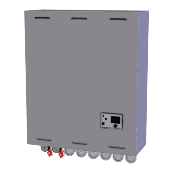
flamco Logotherm LogoMini G2 Installation And Servicing Instruction (68 pages)
Indirect, wall-mounted, thermally insulated, compact local and heat interface units
Brand:
flamco
| Category:
Recording Equipment
| Size: 15 MB
Table of Contents
Table of Contents
2
List of Abbreviations
4
Safety Instructions
5
Intended Use
6
Use for Intended Purpose
6
Improper Use
7
Device Designation
7
Hazard Notes
7
What to Do in the Event of Breakdown or Leaks
8
Spare Parts
9
Requirements on Trained Engineers
9
Liability and Copyrights
9
Earth Bonding or Protective Earthing in Accordance with VDE
9
Description and Technical Data
10
Features
10
Product Designations
11
Summary of the Standardised Station Variants
11
Technical Data of the Heat Interface Unit
12
Design and Components
13
Housing and Thermal Insulation
13
Description of the Variants
14
Heat Interface Unit Variant 1 (M10830.010)
14
Components
14
Dimensions
14
Hydraulic Diagram
15
Wiring Diagram
15
Heat Interface Unit Variant 2 (M10830.210)
16
Components
16
Dimensions
16
Hydraulic Diagram
17
Wiring Diagram
17
Heat Interface Unit Variant 3 (M10830.220)
18
Components
18
Dimensions
18
Hydraulic Diagram
19
Wiring Diagram
19
Heat Interface Unit Variant 4 (M10830.510)
20
Components
20
Dimensions
20
Hydraulic Diagram
21
Wiring Diagram
21
Heat Interface Unit Variant 5 (M10830.520)
22
Components
22
Dimensions
22
Hydraulic Diagram
23
Wiring Diagram
23
Heat Interface Unit Variant 6 (M10830.530)
24
Components
24
Dimensions
24
Hydraulic Diagram
25
Wiring Diagram
25
Heat Interface Unit Variant 7 (M10930.010)
26
Components
26
Dimensions
26
Hydraulic Diagram
27
Wiring Diagram
27
Legend
28
Installation
30
Installation Instructions for Mounting, Connecting and Cable Routing Options
30
Installation Instructions
31
Individual Components
33
Electronic System Controller
33
Primary Components
34
Relay Valves and Controllers
34
Shut-Off, Thermometer and Manometer and Components
36
Secondary Components
37
Space Heating Circuit / Tank Charging Pump
37
Shut-Off Valves
38
Other Components
39
Filter/Strainer in Primary/Secondary Circuit
40
Accessories
41
Installation of Optional Heat Meters in the Primary Heating Circuit
41
Spare Parts
43
Commissioning
43
Flushing and Filling
44
Initial Start-Up
44
Heating System
45
Domestic Water Heater
45
Adjusting the Digital Controller
46
Notes on Thermostatically Controlled Station Variant 7 (M10930.010)
46
Maintenance and Service
47
Information Regarding Domestic Water Hardness
48
Seized Grundfos Pumps, Type UPM3
48
Design Diagrams
50
Summary
50
Primary Flow Rates and Return Line Temperatures
51
Flow and Pressure Losses and Available Differential Pressure
59
Diagrams for Logomini G2 Variants 1
59
Diagrams for Logomini G2 Variant 7
63
Decommissioning, Dismantling, Disposal, Environmental Protection and Disposal of
66
Advertisement
Advertisement
Related Products
flamco Logotherm LogoTronic Hub OTC
flamco Logotherm LogoThermic G2
flamco Logotherm LogoDistrict S
flamco Logotherm LogoDistrict M
flamco Logotherm LogoDistrict L
flamco Logotherm LogoComfort 500
flamco Logotherm LogoComfort 600
flamco Logotherm LogoFresh XL-Line
flamco Meibes A1CX Series
flamco Categories
Water Filtration Systems
Water Pump
Control Unit
Water System
Heating System
More flamco Manuals
Login
Sign In
OR
Sign in with Facebook
Sign in with Google
Upload manual
Upload from disk
Upload from URL