
Related Manuals for flamco Logotherm LogoMini G2

Summary of Contents for flamco Logotherm LogoMini G2
- Page 1 Logotherm LogoMini G2 Indirect, wall-mounted, thermally insulated, compact local and heat interface units S-Line, up to 20 kW Installation and servicing instructions www.flamcogroup.com/manuals...
-
Page 2: Table Of Contents
Table of contents List of abbreviations......................4 Safety instructions ....................5 Intended use ........................6 1.1.1 Use for intended purpose ........................ 6 1.1.2 Improper use ............................ 7 Device designation ......................7 Hazard notes ........................7 What to do in the event of breakdown or leaks ..............8 Spare parts ......................... - Page 3 3.2.6 Heat interface unit variant 6 (M10830.530) ................... 24 3.2.6.1 Components ............................24 3.2.6.2 Dimensions ............................24 3.2.6.3 Hydraulic diagram ..........................25 3.2.6.4 Wiring diagram ............................25 3.2.7 Heat interface unit variant 7 (M10930.010) ................... 26 3.2.7.1 Components ............................26 3.2.7.2 Dimensions ............................
-
Page 4: List Of Abbreviations
List of abbreviations Abbreviation Definitions Flow line Return line Energy meter Male thread Female thread prim. Primary side (from the heat generator) sec. Secondary side (to the heat consumer) Technical Connection Conditions* Safety temperature monitor Domestic water heater (tank charging/continuous flow principle) Domestic water Domestic hot water Domestic water circulation (DHWC) -
Page 5: Safety Instructions
1. Safety instructions Please follow the safety instructions below carefully to prevent hazards and injury to persons and property. These operating instructions are primarily designed for the safe use and installation of the device and make no claims to completeness. These operating instructions describe the functionality of the device and are intended to provide information about the required safety instructions and to draw attention to possible hazards. -
Page 6: Intended Use
Permissible mains supply and operating parameters - Heating side/primary side: Permissible pressure rating: Max. PN10 permissible operating temperature: 110°C - Heating side/secondary side: Permissible pressure rating: Max. permissible operating temperature: 90°C (partially pump-dependent) - Sanitary side*/secondary side: Permissible pressure rating: Max. permissible operating temperature: 90 °C Min. -
Page 7: Improper Use
Caution: Do not make any changes to the electrical components, the design of the equipment or the hydraulic components! This would adversely impact on the safe function of the equipment. Instructions concerning the place of use: Before using our products, they must be checked regarding their suitability for the respective application. -
Page 8: What To Do In The Event Of Breakdown Or Leaks
When the system is in operation, water-regulating components will be hot. Touching these system components can lead to scalding. The heat interface units must be operated with thermal insulation. The thermal insulation is integrated into the units' housing. The housing insulation not only prevents unnecessary heat dissipation, but also protects against accidental contact and burns. -
Page 9: Spare Parts
1.5 Spare parts All spare parts to be used, must correspond to the technical requirements defined by Meibes System- Technik GmbH. This is guaranteed only by using genuine spare parts. The manufacturer is not liable for damage caused by the use of unapproved spare parts or ancillary materials. Appropriate spare parts can be found in our documentation. -
Page 10: Description And Technical Data
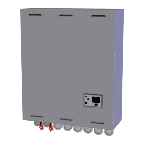
2. Description and technical data The LogoMini G2 are compact heat interface units for the supply of district heating to indirect systems. The models are wall-mounted with an EPP thermally insulated sheet metal housing. The primary and secondary connections are located at the bottom. -
Page 11: Product Designations
2.2 Product designations Key to product designations: Example representation of a product code* LogoMini G2 S-Line I-HW MC-UC -DPC -DHWC -SA Type of controller: SA: Samson DWC integrated: DHWC present Differential pressure regulator: DPC: Present on the primary side Type of heating circuit: MC: mixed UC: unmixed... -
Page 12: Technical Data Of The Heat Interface Unit
2.4 Technical data of the heat interface unit LogoMini G2, S-Line Variants Rated output** 10 kW / 20 kW Heating / DWH 45 kW Max. dimensions Approx. 940 x 780 x 290 mm (without BV), H = approx. 1070 mm (with BV) (H x W x D) Weight Approx. -
Page 13: Design And Components
3. Design and components 3.1 Housing and thermal insulation Sheet metal cover and EPP thermal insulation The units' housing comprises of several components. The front sheet metal covers with permanently integrated insulating plates (V1) and thermal insulation shells of the plate heat exchangers (V3) minimise heat losses and at the same time allow cooling of the unit's electronics. -
Page 14: Description Of The Variants
3.2 Description of the variants 3.2.1 Heat interface unit variant 1 (M10830.010) 3.2.1.1 Components 3.2.1.2 Dimensions LogoMini G2 Manual... -
Page 15: Hydraulic Diagram
3.2.1.3 Hydraulic diagram Heat interface unit variant 1 (M10830.010) 3.2.1.4 Wiring diagram Heat interface unit variant 1 (M10830.010): We reserve the right to change the designs and technical specifications of our products. -
Page 16: Heat Interface Unit Variant 2 (M10830.210)
3.2.2 Heat interface unit variant 2 (M10830.210) 3.2.2.1 Components 3.2.2.2 Dimensions LogoMini G2 Manual... -
Page 17: Hydraulic Diagram
3.2.2.3 Hydraulic diagram Heat interface unit variant 2 (M10830.210) 3.2.2.4 Wiring diagram Heat interface unit variant 2 (M10830.210): We reserve the right to change the designs and technical specifications of our products. -
Page 18: Heat Interface Unit Variant 3 (M10830.220)
3.2.3 Heat interface unit variant 3 (M10830.220) 3.2.3.1 Components 3.2.3.2 Dimensions LogoMini G2 Manual... -
Page 19: Hydraulic Diagram
3.2.3.3 Hydraulic diagram Heat interface unit variant 3 (M10830.220) 3.2.3.4 Wiring diagram Heat interface unit variant 3 (M10830.220): We reserve the right to change the designs and technical specifications of our products. -
Page 20: Heat Interface Unit Variant 4 (M10830.510)
3.2.4 Heat interface unit variant 4 (M10830.510) 3.2.4.1 Components 3.2.4.2 Dimensions LogoMini G2 Manual... -
Page 21: Hydraulic Diagram
3.2.4.3 Hydraulic diagram Heat interface unit variant 4 (M10830.510) 3.2.4.4 Wiring diagram Heat interface unit variant 4 (M10830.510): We reserve the right to change the designs and technical specifications of our products. -
Page 22: Heat Interface Unit Variant 5 (M10830.520)
3.2.5 Heat interface unit variant 5 (M10830.520) 3.2.5.1 Components 3.2.5.2 Dimensions LogoMini G2 Manual... -
Page 23: Hydraulic Diagram
3.2.5.3 Hydraulic diagram Heat interface unit variant 5 (M10830.520) 3.2.5.4 Wiring diagram Heat interface unit variant 5 (M10830.520): We reserve the right to change the designs and technical specifications of our products. -
Page 24: Heat Interface Unit Variant 6 (M10830.530)
3.2.6 Heat interface unit variant 6 (M10830.530) 3.2.6.1 Components 3.2.6.2 Dimensions LogoMini G2 Manual... -
Page 25: Hydraulic Diagram
3.2.6.3 Hydraulic diagram Heat interface unit variant 6 (M10830.530) 3.2.6.4 Wiring diagram Heat interface unit variant 6 (M10830.530): We reserve the right to change the designs and technical specifications of our products. -
Page 26: Heat Interface Unit Variant 7 (M10930.010)
3.2.7 Heat interface unit variant 7 (M10930.010) See note regarding the thermostatically controlled unit variant: Section 6.6 3.2.7.1 Components 3.2.7.2 Dimensions LogoMini G2 Manual... -
Page 27: Hydraulic Diagram
3.2.7.3 Hydraulic diagram Heat interface unit variant 7 (M10930.010) 3.2.7.4 Wiring diagram Heat interface unit variant 7 (M10930.010): We reserve the right to change the designs and technical specifications of our products. -
Page 28: Legend
3.3 Legend Components Item Components/elements Notes Type B15x40 Type WP24-30 Stainless steel plate heat exchanger (copper brazed) with thermal insulation to the DWH in the continuous flow principle Differential pressure regulator (fixed setpoint value) Kv=2.5 with volumetric flow limiter in the primary return line Control valve with actuator in the primary return line Strainer/filter, with male screwed 1"... - Page 29 Check valve / backflow preventer in secondary flow line, after pumps 3 bar, secondary heating circuit Safety valve ½" x ¾" 16b* 6 bar, CW domestic water Vent stoppers ½" Primary Fill and drain ball valve ½" with cap Secondary Venting stoppers / sensor mounting option HFM Primary, return line to the DWH...
-
Page 30: Installation
4. Installation General assembly instructions Sufficient space for installation, maintenance and service Installation on a suitable load-bearing wall with appropriate fastening materials Re-tighten all joints and screw fittings during a pressure test or following the initial heating cycle General assembly instructions for protecting the pump When installing the station, please also refer to the instructions of the pump manufacturer: Only install a pump shaft horizontally Note the minimum supply pressures: e.g. -
Page 31: Installation Instructions
4.2 Installation instructions The stations may only be installed and commissioned by qualified specialists in consultation with the relevant district heating provider. The connecting pipework must be selected to ensure it satisfies the statutory requirements with regard to material, pressure, temperature and chemical resistance (see “Technical Connection Conditions”... - Page 32 Connection to the domestic water system: The heat interface unit may only be connected to the domestic water system by specialist companies authorised by the local domestic water supplier. The heating system must only be filled using a DVGW-approved filling device (see also VDI 2035). Disconnect this filling device as soon as filling is complete.
-
Page 33: Individual Components
5. Individual components 5.1 Electronic system controller For controlling the primary side, included are 2x temperature sensors (primary return line and secondary flow line), a controller from Samson, type Trovis 5573, is mounted and electrically connected at the factory. The secondary-side control circuits are also connected and configured (corresponding to the station variant). -
Page 34: Primary Components
5.2 Primary components 5.2.1 Relay valves and controllers Primary fittings in the flow to the DHW* Item No. ET No. (21)* 2-way valve with 2-point actuator ME-80590.45 to the primary domestic hot water tank charging system Type Danfoss, straight-way valve ¾"... - Page 35 Primary fittings and components in the return line Item No. ET No. 2-way ball valve with 3-point 230 V actuator Type Belimo, R408DK DN10; Kvs=1.6; ¾" ME-80594.06 male thread with actuator TRD230-007; ME-80594.07 230V; 1.6 Nm (2)* Differential pressure regulator / flow limiter (with fixed setpoint value) Type Danfoss, AVPB-F, PN16, DN15, Kvs=2.5;...
-
Page 36: Shut-Off, Thermometer And Manometer And Components
5.2.2 Shut-off, thermometer and manometer and components Primary fittings and components in the flow line and return line Item No. ET No. (5a) District heating circuit shut-off ME-61881.24 valves Ball valves ¾" FT x ¾" UN with mounting option for sensor (M10x1) from the front (for optional heat meter) and with sealing option... -
Page 37: Secondary Components
5.3 Secondary components 5.3.1 Space heating circuit / tank charging pump Item No. 12a, b, c) type Grundfos UPM3 Hybrid 15-70 130 PWM (ET No.: ME-45101.76) The additional enclosed documents concerning the pump must be observed. Depending on the system, the pump must be adjusted/adapted to the requirements on site. Electrical data: Power supply: 230 V, 50 Hz Speed... -
Page 38: Shut-Off Valves
5.3.2 Shut-off valves Item No. Shut-off valves for secondary tank charging circuit and for ET No. heating circuits* (6b) Ball Valve with backflow limiter: (7b) ME-61887.55 (15) Ball Valve without backflow limiter: ME-61887.56 Thermometer red/blue: ME-58071.504/ ME-58071.505 Thermometer 0…120°C (red/ Blue), removable ball valve handles (¾"... -
Page 39: Other Components
5.3.3 Other components Item No. Other components in Descriptions ET No. the secondary circuit Flexvent bleed valve 3/8" x ½" with shut-off ME-67502.1 option installed in the heating circuit flow line. Prescor safety valve 3 bar ½" x ¾" and gauge ME-69010.01 0…4 bar with centred connection, installed in ME-69021.10... -
Page 40: Filter/Strainer In Primary/Secondary Circuit
Flow rate limiter 17 litres/min (identifying ME-10240.801 colour: brown), installed in the domestic with cold water. ME-10240.805 DVGW, WRAS domestic water ball valve ¾" ME-61801.22 female thread x UN ¾" female thread with red removable handle 10b 10c* Screw-in temperature sensor T½" NL=45 ME-10576.113 *Depending on station variant The outlet lines of the safety valves run from the unit housing downwards and must not be sealed. -
Page 41: Accessories
5.5 Accessories Fig. Optional accessory parts Art. No. LogoMini drainage set M10730.010 LogoMini flushing set M10730.030 HFM counter holder M10730.020 Heat flow meter from See website or the latest the "HeatSonic" or product catalogue "LogoSonic" series 5.6 Installation of optional heat meters in the primary heating circuit A heat meter (HFM) may only be installed once the entire heating system has been flushed through. - Page 42 Procedure (example): Close all 7a or 7b* shut-off valves on the primary side. Lower the system pressure by opening the bleeding devices (e.g. 17a). WARNING: Water may leak from the system. (The station can be drained using the optional fill and drain ball valves.) Then loosen the screw fittings on adapter 14a or 14b*.
-
Page 43: Spare Parts
5.7 Spare parts Designation Order No. Surface-mounted cover, galv. sheet steel (HxWxD) 920x780x280 mm incl. ME-10203.785 rapid closures Sealing set ¾" and 1" ME-43.6615 Stainless steel corrugated tube set DN20 for secondary circuit with thermal insulation ME-46122 Stainless steel corrugated tube set DN16 for secondary circuit with thermal insulation ME-46123 Stainless steel corrugated tube set DN16 for primary circuit with thermal insulation ME-46123F Service kit for heat interface unit connection ¾"... -
Page 44: Flushing And Filling
6.1 Flushing and filling Note for the installer: Heating systems must be flushed prior to commissioning in accordance with local regulations, such as DIN EN 14336, VOB ATV C DIN 18380 or VDI 2035. After the system has been filled for the first time, the recirculation pump must be left to run for about 1 hour before it can be switched off for a longer period. -
Page 45: Heating System
6.3 Heating system Commission the system according to the following points (general instructions): (The system is disconnected from the mains and empty.) Close the shut-off valves on the primary and secondary sides. Flush, fill and bleed the primary side. Check for leaks. Flush, fill and bleed the secondary side. -
Page 46: Adjusting The Digital Controller
6.5 Adjusting the digital controller If the heat interface unit is supplied with a digital controller, the controller controls the system according to the outside temperature or the demand for domestic water, while simultaneously restricting the return temperature on the primary side. Note: Depending on the configuration of the controller, it is possible to prioritise the hot water or run it in parallel with the heating circuit. -
Page 47: Maintenance And Service
If you have any questions, please contact your installation company or Flamco customer service. Extract from DIN 4747-1: "The operator of domestic heat interface units is obligated to have the system maintained at regular intervals by a qualified person. -
Page 48: Information Regarding Domestic Water Hardness
7.1 Information regarding domestic water hardness The propensity for natural water to form limescale deposits depends, among other things, on various factors such as the concentration of calcium and magnesium salts, the pH value and the temperature. If what is known as the lime-carbonic acid balance has been disturbed by an increase in the pH value and/or the temperature, the calcium carbonate precipitates in the form of calcite crystals. - Page 49 Notes: Downtimes should generally be avoided. (Magnetic) Dirt and air separators must be installed properly in the system so that they work correctly. Freedom from oxygen (air) in the system must be constantly ensured. The medium used must always correspond to VDI 2035.
-
Page 50: Design Diagrams
Design diagrams 8.1 Summary Diagrams for heating via plate heat exchanger, type B15x40 (item 1a) Heating Primary flow rate required Return temperature of the primary side secondary side for heating secondary side, in the case of heating on the secondary side, depending on the flow line temperature depending on the flow line temperature by 10K... -
Page 51: Primary Flow Rates And Return Line Temperatures
Available differential pressure Circuit Heat interface unit 1 to 6 variants Tank charging circuit Diagram 21 Secondary Diagram 22 Diagram 28 MC (straight Diagram 23 8.2 Primary flow rates and return line temperatures Diagram 1 LogoMini B15x40: Primary flow rate required for secondary side heating by 10K (from 35°C to 45°C) depending on the flow line temperature (FL-T.) We reserve the right to change the designs and technical specifications of our products. - Page 52 Diagram 2 LogoMini B15x40: Return line temperature on the primary side for secondary side heating by 10K (from 35°C to 45°C) depending on the flow line temperature (FL-T.) Diagram 3 LogoMini B15x40: Primary flow rate required for secondary side heating by 7K (from 30°C to 37°C) depending on the flow line temperature (FL-T.) LogoMini G2 Manual...
- Page 53 Diagram 4 LogoMini B15x40: Return line temperature on the primary side for secondary side heating by 7K (from 30°C to 37°C) depending on the flow line temperature (FL-T.) Diagram 5 LogoMini B15x40: Primary flow rate required for secondary side heating by 20K (from 45°C to 65°C) depending on the flow line temperature (FL-T.) We reserve the right to change the designs and technical specifications of our products.
- Page 54 Diagram 6 LogoMini B15x40: Return line temperature on the primary side for secondary side heating by 20K (from 45°C to 65°C) depending on the flow line temperature (FL-T.) Diagram 7 LogoMini B15x40: Primary flow rate required for secondary side heating by 15K (from 45°C to 60°C) depending on the flow line temperature (FL-T.) LogoMini G2 Manual...
- Page 55 Diagram 8 LogoMini B15x40: Return line temperature on the primary side for secondary side heating by 15K (from 45°C to 60°C) depending on the flow line temperature (FL-T.) Diagram 9 LogoMini WP24-30: Primary flow rate required for domestic water heating by 35K (from 10°C to 45°C) depending on the flow line temperature (FL-T.) We reserve the right to change the designs and technical specifications of our products.
- Page 56 Diagram 10 LogoMini WP24-30: Return line temperature on the primary side for domestic water heating by 35K (from 10°C to 45°C) depending on the flow line temperature (FL-T.) Diagram 11 LogoMini WP24-30: Primary flow rate required for domestic water heating by 40K (from 10°C to 50°C) depending on the flow line temperature (FL-T.) LogoMini G2 Manual...
- Page 57 Diagram 12 LogoMini WP24-30: Return line temperature on the primary side for domestic water heating by 40K (from 10°C to 50°C) depending on the flow line temperature (FL-T.) Diagram 13 LogoMini WP24-30: Primary flow rate required for domestic water heating by 45K (from 10°C to 55°C) depending on the flow line temperature (FL-T.) We reserve the right to change the designs and technical specifications of our products.
- Page 58 Diagram 14 LogoMini WP24-30: Return line temperature on the primary side for domestic water heating by 45K (from 10°C to 55°C) depending on the flow line temperature (FL-T.) Diagram 15 LogoMini WP24-30: Primary flow rate required for domestic water heating by 50K (from 10°C to 60°C) depending on the flow line temperature (FL-T.) LogoMini G2 Manual...
-
Page 59: Flow And Pressure Losses And Available Differential Pressure
Diagram 16 LogoMini WP24-30: Return line temperature on the primary side for domestic water heating by 50K (from 10°C to 60°C) depending on the flow line temperature (FL-T.) 8.3 Flow and pressure losses and available differential pressure 8.3.1 Diagrams for LogoMini G2 variants 1…6 Diagram 17 We reserve the right to change the designs and technical specifications of our products. - Page 60 Diagram 18 Diagram 19 LogoMini G2 Manual...
- Page 61 Diagram 20 Diagram 21 We reserve the right to change the designs and technical specifications of our products.
- Page 62 Diagram 22 Diagram 23 LogoMini G2 Manual...
-
Page 63: Diagrams For Logomini G2 Variant 7
8.3.2 Diagrams for LogoMini G2 variant 7 Diagram 24 Diagram 25 We reserve the right to change the designs and technical specifications of our products. - Page 64 Diagram 26 Diagram 27 LogoMini G2 Manual...
- Page 65 Diagram 28 We reserve the right to change the designs and technical specifications of our products.
-
Page 66: Decommissioning, Dismantling, Disposal, Environmental Protection And Disposal Of
Decommissioning, dismantling, disposal, environmental protection and disposal of electrical and electronic equipment During dismantling, the safety instructions and residual dangers mentioned (see Section 1) must be observed! Removal and disposal: Removal and disposal of the device should only be carried out by suitable trained experts. When disposing of the auxiliary and operating materials, always observe the specifications in the safety data sheets, which must be provided by the suppliers of the auxiliary and operating materials. - Page 67 separately as batteries or lamps. Data privacy We would like to point out to all end users of electrical and electronic equipment that you are responsible for deleting personal data on the electrical and electronic equipment to be disposed *Please observe the country-specific national implementation of the European WEEE Directive 2012/19/ EU on waste electrical and electronic equipment that is currently in force.
- Page 68 Copyright Flamco B.V., Almere, the Netherlands. No part of this publication may be reproduced or published in any way without explicit permission and mention of the source. The data listed are solely applicable to Flamco products. Flamco B.V. shall accept no liability whatsoever for incorrect use, application or...
Need help?
Do you have a question about the Logotherm LogoMini G2 and is the answer not in the manual?
Questions and answers