Sign In
Upload
Manuals
Brands
Fire-Lite Alarms Manuals
Control Panel
MS-9200UDE
User Manuals: Fire-Lite Alarms MS-9200UDE Control Panel
Manuals and User Guides for Fire-Lite Alarms MS-9200UDE Control Panel. We have
1
Fire-Lite Alarms MS-9200UDE Control Panel manual available for free PDF download: Manual
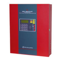
Fire-Lite Alarms MS-9200UDE Manual (192 pages)
Fire Alarm Control Panel
Brand:
Fire-Lite Alarms
| Category:
Control Panel
| Size: 4 MB
Table of Contents
Table of Contents
5
SECTION 1: Product Description
12
Features and Options
12
Specifications
14
1: Current Availability
15
Controls and Indicators
16
Circuits
17
Digital Alarm Communicator/Transmitter
17
Components
18
1: Intelligent Addressable Detectors: Newer Series
18
2: Intelligent Addressable Modules: Newer Series
19
3: 300 Series Intelligent Addressable Devices
20
4: Addressable Device Accessories
20
Optional Modules
21
Accessories
21
1: PK-Plus Programming Utility
21
2: Dress Panel
21
3: Battery Box
22
4: Battery Charger
22
CHG-120F Battery Charger
22
5: Annunciators
23
Getting Started
24
Telephone Requirements and Warnings
25
1: Telephone Circuitry
25
2: Digital Communicator
25
3: Telephone Company Rights and Warnings
26
SECTION 2: Installation
27
Mounting Backbox
27
Mounting Transformer
28
Power
31
1: AC Power and Earth Ground Connection
31
2: Battery Power
31
3: DC Power Output Connection
31
Relays
32
Notification Appliance Circuits
32
1: Configuring Nacs
33
2: Style y (Class B) NAC Wiring
33
3: Style Z (Class A) NAC Wiring
34
Remote Synchronization Output
34
UL Power-Limited Wiring Requirements
35
Digital Communicator
36
Optional Module Installation
37
1: 4XTMF Transmitter Module Installation
38
2: Printer/Pc
40
3: Digital Communicator and Annunciators
41
ACM-8RF Relay Control Module
41
BRKT-9600 Universal Bracket Installation
41
ACM and AFM Series Annunciators
43
SECTION 3: Programming
44
Programming Data Entry
44
User Programming
45
Initial Power-Up
46
Programming Screens Description
46
Programming and Passwords
46
Master Programming Level
48
1=Autoprogram
49
2=Point Program
50
Detector Programming
50
Add Detector
50
Delete Detector
51
Edit Detector
51
Module Programming
60
Add Module
60
Delete Module
61
Edit Module Screen for Monitor Module
61
Edit Module Screen for Control Modules
70
3=Zone Setup
77
Enable
77
Disable
78
Zone 97, 98 and 99
78
Zones Installed
79
Zones Enabled
79
Zones Disabled
79
Zone Type
80
Zones Available
81
4: Loop Setup
81
Style
81
Loop Protocol
81
5: System Setup
82
Trouble Reminder
83
Banner
83
Time-Date
84
Time
84
Date
85
Clock Format
85
Daylight Savings Time
85
Timers
86
PAS (Positive Alarm Sequence) Delay
86
Presignal Delay
87
Waterflow Delay
87
AC Loss Delay
88
NAC (Notification Appliance Circuit)
88
Enabled
89
Type
90
Silenceable
90
Auto Silence
91
Coding (Only for Nacs Not Programmed as Sync Strobe Type)
91
Zone
92
Silence Inhibited
92
Sync Type
92
Relays
93
Canadian Option
94
Waterflow Silenceable
94
6: Verify Loop
94
7: History
95
View Events
95
Erase History
95
8: Walktest
96
9: Option Modules
97
Annunciators/Udact
97
Onboard DACT
98
Onboard DACT Enable
98
Primary Phone
99
Secondary Phone
99
Service Terminal
100
Central Station
102
Trouble Call Limit (Dialer Runaway Prevention)
103
Manual Dial Mode
115
Printer/Pc
116
10: Password Change
117
11: Clear Program
118
12: Program Check
119
Maintenance Programming Level
121
1: Disable Point
122
2=History
123
3=Program Check
124
4: Walktest
125
5: System
125
6: Zone Setup
127
SECTION 4: Operating Instructions
129
Panel Control Buttons
129
1: Acknowledge/Step
129
2: Alarm Silence
129
3: Drill/Hold 2 Sec
129
4: Reset
129
LED Indicators
130
Normal Operation
131
Trouble Operation
131
Alarm Operation
133
Supervisory Operation
134
Process Monitor Operation
135
Hazard/Tornado Condition Operation
135
Medical Alert Condition Operation
135
NAC Operation
135
Programmed Zone Operation
136
Disable/Enable Operation
136
Waterflow Circuits Operation
136
Detector Functions
136
Time Functions: Real-Time Clock
136
Synchronized NAC Operation
137
Coded Operation
137
Presignal
137
Positive Alarm Sequence
138
Special System Timers
139
1: Silence Inhibit Timer
139
2: Autosilence Timer
139
3: Trouble Reminder
139
4: Waterflow Retard Timer
139
5: Alarm Verification (None or One Minute)
140
Walktest
140
Read Status
141
1: System Point
142
2: Zones
143
3: Power
144
4: Trouble Reminder
145
5: Timers
145
6: Nac
146
7: Relays
146
8: Program Check
147
9: History
147
10: Annunciators
148
11: Phone Line
148
12: Central Station
149
13: Service Terminal
150
14: Printer/Pc
150
15: Print
151
16: Time-Date
153
SECTION 5: Central Station Communications
154
Transmittal Priorities
157
SECTION 6: Remote Site Upload/Download
159
Downloading Program
159
1: Security Features
160
Downloading Initiated at Control Panel
162
Downloading Initiated at a Service Terminal
162
Uploading Initiated at a Service Terminal
163
SECTION 7: Power Supply Calculations
164
Overview
164
Calculating the AC Branch Circuit
164
Calculating the System Current Draw
165
1: Overview
165
2: How to Use Table 7.3 on Page 166 to Calculate System Current Draw
165
Calculating the Battery Size
167
1: NFPA Battery Requirements
167
2: Selecting and Locating Batteries
167
APPENDIX A: Software Zones
168
A.1: Correlations
168
APPENDIX B: Default Programming
174
APPENDIX C: NFPA Standard-Specific Requirements
175
APPENDIX D: Wire Requirements
179
Advertisement
Advertisement
Related Products
Fire-Lite Alarms MS-9200UD
Fire-Lite Alarms MS-9200E
Fire-Lite Alarms MS-9600LS
Fire-Lite Alarms MS-9600UDLSE
Fire-Lite Alarms MS-9600LSC
Fire-Lite Alarms MS-9600LSE
Fire-Lite Alarms MS-9600UDLS
Fire-Lite Alarms MS-4424B
Fire-Lite Alarms MS-5210UDE
Fire-Lite Alarms MS-5024UD
Fire-Lite Alarms Categories
Smoke Alarm
Control Panel
Fire Alarms
Accessories
Power Supply
More Fire-Lite Alarms Manuals
Login
Sign In
OR
Sign in with Facebook
Sign in with Google
Upload manual
Upload from disk
Upload from URL