Sign In
Upload
Manuals
Brands
Fike Manuals
Control Systems
CyberCat 1016
Fike CyberCat 1016 Manuals
Manuals and User Guides for Fike CyberCat 1016. We have
3
Fike CyberCat 1016 manuals available for free PDF download: Operation & Maintenance Manual, Programming Manual, Installation Manual
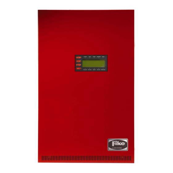
Fike CyberCat 1016 Operation & Maintenance Manual (136 pages)
Addressable Fire Alarm Control System
Brand:
Fike
| Category:
Control Systems
| Size: 3 MB
Table of Contents
Table of Contents
3
Section Description Page
4
1 Introduction
9
About this Manual
9
Product Support
9
Safety Information
9
Related Documentation
9
Understanding Cybercat
10
System Controller
10
Intelligent Addressable Devices
10
Peripheral Devices
10
Emergency Communication System
11
UL (90.23) Operational Limitations
12
2 User Interface
53
Cybercat Main Display
53
System Status Leds
54
Status Leds
54
Status LED Descriptions
54
History Navigation Buttons
55
Control Buttons
55
Navigation and Function Buttons
56
LCD Display
57
System Normal Display
57
System Event Display
58
Top Level Menu
59
Password Protection
60
Password Access Levels
60
Logging Onto the System
61
Changing the System Administrator Password
61
Password Entry Screen
61
3 System Operation
63
General Operation
63
AC Trouble Delay
63
Daylight Savings
63
Silence Inhibit
63
Silence Reminder
64
State Counters
64
Network Operation
64
IP Network
64
Positive Alarm Sequence
65
Smoke Control Operation
65
Emergency Communication System
65
Voice System Priorities
66
Panel Menu Structure
67
Panel Operation by Event
67
Power-Up Reset
67
Record New Device Display
67
Power-Up Reset Display
67
Normal State
68
System Normal Display
68
Alarm/Waterflow State
69
Alarm Display
69
Alarm Verification
70
Alarm Verification Display
70
Summing Alarm State
71
Summing Alarm Display
71
Trouble State
72
Trouble Display
72
Supervisory State
73
Supervisory Display
73
Pre-Alarm State
74
Process State
75
Process Display
75
Zone Disable State
76
Drill State
77
Drill Display
77
Walk-Test Operation
78
Fan Restart Operation
79
CRM4 Fan Restart Operation
79
Addressable Relay Fan Restart Operation
80
AHU Fire Key
80
Intelligent Detector Features
81
Alarm Verification
81
Pre-Alarm
81
Detector Programming Features
81
Acclimate
82
Drift Compensation
82
Day/Night/Holiday Settings
82
Flame Enhance
82
Summing
83
Smolder
83
Walk-Test
83
4 System History
85
Overview
85
Viewing History
85
Top Level Menu
86
History Menu
86
Alarm History
87
Supervisory History
87
Alarm History Screen
87
Supervisory History Screen
87
Trouble History
88
Events History
88
Zone History
89
Erase History
89
Zone History Screen
89
Erase History Status
89
Viewing Additional Event Information
90
5 System Diagnostics
91
Overview
91
Diagnosing Problems
91
Removing or Replacing Panel Components
91
Diagnostic Menu 1
92
Device Diagnostic
92
Device Diagnostic Menu
92
Device Type, Location and LED Diagnostics
93
Device Type Diagnostic Screen
93
Device Serial Number Diagnostic
94
Device S/N Diagnostic Screen
94
Value 1 Diagnostic
95
Value 2 Diagnostic
96
LED Test
97
CRC (Cyclic Redundancy Count)
97
Diagnostic Menu 2
97
Keypad Diagnostics
98
VESDA 1 Diagnostics
98
Diagnostic Menu 2
98
Keypad Diagnostics Screen
98
VESDA 1 Diagnostics Screen
98
VESDA 2 Diagnostics
99
Peripheral Diagnostics
99
Fire-Phone Diagnostics
100
Vesdanet Communications
101
Auxiliary Switch Cards Diagnostics Screen
101
Vesdanet Communication Screen
101
Diagnostic Menu 3
102
Diagnostic Menu 3
103
Network Reset
104
Network Diagnostics 1 Screen
104
Network Diagnostics 3 Screen
104
Network Reset Screen
104
Network Diagnostic 3
104
History Diagnostics
105
History Diagnostics Screen
105
Board Communication Diagnostics
106
Diagnostic Menu 4
106
Amplifier Status
107
Amplifier Operation Status Screen
107
Peripheral Supervision Data
108
Peripheral Supervision Data Screen
108
Voice Zones
111
Voice Zones Priorities
112
Voice Zones Status
112
Voice Zones Status Screen
112
Peripheral Firmware Version
113
Diagnostic Menu 5
114
Page Status
114
Audio Priority Status
115
Audio Priority Status Screen
115
Play Message ID Status
116
Play Message ID Status Screen
116
FAAST Detector Status
117
FAAST Detector Selection Screen
117
FAAST Detector Status Screen
117
Voltages
118
Control Board Test Points
118
6 System Maintenance
119
Overview
119
Routine Maintenance
119
Fuse Replacement
120
Controller Fuse Locations
120
SPS Fuse Locations
120
Panel Maintenance Menus
121
Device Read
121
Maintenance Menu 1
121
Maintenance Menu
121
Device Address
122
Device Address Screen
122
Device Address Process Screen
122
Device Replace
123
Device Address/New Device Screen
123
Device Address/Change Screen
123
Device Replace Menu
123
Retrieving Configuration Screen
124
Device Replace Screen
124
Device Configuration Screen
124
Device Replace Success Screen
124
Walk-Test
125
Panel Walk-Test
126
IR Tool Walk-Test
127
Buzzer
127
Maintenance Menu 2
128
Mass Notification System Reset
128
MNS Reset Screen
128
Mass Notification System Silence
129
Switch Operation
129
MNS Silence Screen
129
Switch Timeout Screen
129
Device Configuration Read
130
Faast
131
AHU on
131
FAAST Screen
131
AHU on Screen
131
Advertisement
Fike CyberCat 1016 Installation Manual (100 pages)
Addressable Fire Alarm Control System
Brand:
Fike
| Category:
Control Systems
| Size: 7 MB
Table of Contents
Table of Contents
4
1 Introduction
11
About this Manual
11
Product Support
11
Safety Information
11
Terms Used in this Manual
12
Related Documentation
13
Related Documentation – Continued
14
2 System Overview
15
System Description
15
Example Cybercat Block Diagram
15
Cybercat Features
16
Listings and Approvals
17
Agency Standards and Compliance
17
Minimum System Configurations
18
3 System Components
21
Basic Equipment Packages
21
Cybercat Controller
21
System Ordering Formats
21
Cybercat System Controller with Display
22
Cybercat Controller Terminal Locations
23
Cybercat Controller Terminal Specifications
24
Cybercat Controller Terminal Specifications – Cont
25
Cybercat Controller Terminal Specifications – Cont
26
Cybercat Controller Terminal Specifications – Cont
27
System Enclosures
28
Enclosure Ordering Formats
28
Standard Enclosure
29
Standard Enclosure with no Dead-Front
29
Standard Enclosure with Solid Dead-Front
30
Standard Enclosure with Three Card Dead-Front
30
FCC Enclosure with Nineteen Card Dead-Front
31
Fire Command Center (FCC) Enclosures
31
FCC Enclosure with Twenty-Three Card Dead-Front
32
Multi-Interface Module
32
FCC Enclosure with Option-2 Back-Box
33
FCC Enclosure with Twenty-Five Card Dead-Front
34
Optional Dead-Front Cover Plates
35
Optional Circuit Modules
36
DACT Programmer
36
DACT, 5 Zone with Serial Interface
36
Supplemental Power Supply (SPS)
36
Relay Module (CRM4)
37
Reverse Polarity Module (RPM)
37
RS485 Network Module
37
Supplemental Loop Module (SLM)
37
Fiber Optic Network Module
38
Fourteen Button Remote Display Unit
39
Ten Button Remote Display Unit
39
Ethernet Module
40
Multi-Interface Module (MIM)
40
Two Button Remote Display Unit
40
Firefighter's Smoke Control Station (FSCS)
41
Intelligent Graphic Annunciator
41
Graphic Annunciator (Intelligent)
41
Twenty Zone Remote Annunciator
42
Six Zone Smoke Control Switch Card
42
Input/Output Switch Card
42
Smoke Control Switch Card
42
I/O Switch Card
42
Twenty Zone Annunciator Card (Panel Mount)
43
Audio Control Card
43
Fire-Phone Card
44
Supplemental Fire-Phone Card
44
Amplifier Card
44
Class a Speaker Card
44
Relay Control Assembly
45
Relay Card
45
Class a Peripheral Bus Card
45
HPM4 Relay Card
45
FCC Digital Paging Assembly
46
Local Operating Console
47
Audio Adjunct Panel
47
LOC W/ RDU
47
Intelligent Detectors
48
Photoelectric Smoke Detector
48
Ionization Smoke Detector
48
Photo Detector
48
Ion Detector
48
Photo/Heat Combination Detector
49
Heat Detector
49
Photo/Heat Detector
49
Photoelectric Duct Detector
50
Duct Detector Housing
50
FAAST Aspirating Smoke Detector
51
FAAST Detector
51
Detector Bases
52
Sounder Base
52
Relay Base
52
4-Inch Base
52
Remote Testing and Notification Accessories
53
Remote Annunciator
53
Remote Test Station
53
Remote Test Station with Key
53
Addressable Modules
54
Mini Monitor Module
54
Monitor Module
55
Dual Monitor Module
55
Addressable Pull Station
55
Conventional Zone Monitor Module
55
Pull Station
55
Supervised Control Module
56
Master-Box Interface
56
Solenoid Protection Assembly
56
Relay Module
57
Vesda High Level Interface
57
Programming and Configuration Equipment
57
IR Remote Tool
57
Vesda Hli
57
Hand Held Programmer
58
C-Linx Software
58
Interface Cable
58
Interface Converter
58
Interface Cable (USB to RS232)
58
Interface Cable (USB)
58
USB Communication Cable
58
Batteries and Battery Enclosures
59
AH Battery Assembly
59
Batteries
59
Battery Enclosures
59
4 Installation
61
System Installation Sequence
61
Select the Enclosure Mounting Location
61
Select the Enclosure Mounting Option
62
Mount the Enclosure
62
Install the Dead-Front Door
62
Standard Enclosure Dimensions
63
FCC Enclosure Dimensions
64
Wire Selection
65
Circuit Class Designations
65
Pull Field Wiring into the Enclosure
65
Verify Field Wiring
66
Install the AC Power Transformer
66
Connect AC Power to the Transformer
67
Connect AC Power to Transformer
68
Install Optional Modules
69
Install the Controller
70
Mounting the Controller
71
Mounting the Extended Display
72
Connect the AC Power to the Controller
73
AC Power Connections
73
Install Batteries
74
Battery Cutoff
74
Battery Connections
74
Apply Power to the Panel
75
Connect Field Wiring
76
Cybercat Board Terminal Connections
76
General Relay Wiring
77
RS232 Wiring
77
RS485 Peripheral Bus Wiring
77
Auxiliary Power Wiring
78
SLC Wiring
79
Class B Wiring
79
Class B SLC Wiring
79
Class X Wiring
80
Remote LED Wiring
80
Class a SLC Wiring
80
Notification Appliance Circuit Wiring
81
Initial Power-Up with Field Wiring Connected
82
Configure System
82
Acceptance Test
82
Appendix A Battery Calculation Form
83
System Operation Posting
87
Operating Instructions
89
Appendix B System Operation Posting
91
Appendix C Compatible Components
91
Compatible Components
91
Appendix D Battery Cutoff
97
fike CyberCat 1016 Programming Manual (128 pages)
Addressable Fire Alarm Control System
Brand:
fike
| Category:
Control Systems
| Size: 0 MB
Table of Contents
Table of Contents
3
Section Description Page
4
1 About this Manual
7
Product Support
7
Safety Information
7
Revision History
8
2 0 C-Linx PROGRAMMING OPTIONS
9
Understanding Cybercat
9
Software Programming Features
10
3 0 Getting Started
51
User Interface
51
Password Protection
52
How to Log Onto the System
53
Changing the System Administrator Password
53
Configuring the System
54
Autoprogram
54
Engineered Configure
54
How to Address a Device
55
How to Auto Address Field Devices
55
How to Use the Panel's Device Address Function
56
New Device Detected Screen
57
How to Address Devices with the IR Tool
58
IR Communication Tool
59
How to Address Devices with the Hand-Held Programmer
60
New Device Detected Screen
61
4 Configuration Menu
65
Configuration Menu 1
65
How to Configure a Field Device
65
How to Change a Devices Alarm Features
66
How to Modify a Sensor
67
How to Modify a Control or Relay Module
67
Any of 3 Zones Function Screen
68
All of 3 Zones Function Screen
69
Configuration Menu 6
70
How to Modify a Monitor Module
71
How to Modify a Pull Station
72
How to Delete a Device from the System Configuration
72
How to Read, Write, Enable or Disable a Device
73
How to Set the AHU Relay Re-Start Delay
74
How to Perform a Configuration Check
75
How to Modify the Panel's NAC Circuits
75
How to Modify NAC Functions
76
How to Set NAC Zone Assignments
77
How to Change SLC Supervision
78
How to Set NAC Sync Protocol
78
How to Set SLC Command Mode Functions
79
How to Execute the Learn Function
80
Learn New Devices Only
80
Learn All Devices
81
How to Enable Panel Voice Operations
82
How to Set Mass Notification Reset Timeout
83
How to Set Voice State Priority Levels
83
Configuration Menu 2
84
How to Set System Time and Date
84
How to Set System Silencing Options
85
How to Set System Power Options
86
Power Screen (Cybercat 1016)
87
How to Modify Daytime Sensitivity Settings
88
How to Set Holiday Settings for Daytime Sensitivity
89
How to Assign a Chime Code to a Zone
90
How to Assign Evacuation Sets to a Zone
91
Configuration Menu 3
92
How to Configure Peripheral Devices
93
Peripheral Device Testing
94
How to Program an Amplifier
95
Amplifier Message Configuration Screen
96
Dual-Channel Speaker Circuit Configuration Screen
97
How to Program a Fire-Phone Module
98
How to Set the Peripheral Bus Command Source
99
How to Set the Peripheral Bus Command Set
100
How to Enable/Disable System Walktest
101
How to Enable/Disable Day/Night Sensitivity Feature
102
How to Set AC Trouble Delay
103
How to Set VESDA Alarm Features
104
How to Set VESDA Sector/Zone Correlation
105
VESDA Command Set Screen
106
How to Set an Auxiliary Power Circuit as an AUX/NAC
107
How to Assign Zones to the AUX/NAC Circuit
108
How to Assign Power Cut-Off Relay Address
109
How to Set Optional Module Mounting Location
110
How to Set the Function of the Panel's On-Board Relays
111
How to Assign Relays to a Zone
112
How to Set Fan Restart Mode
113
How to Change System Logo
114
How to Configure Dialer Test
115
How to Set Panel's Network ID
116
How to Configure Network Module
117
How to Assign Panel to Network Zones
118
How to Set the Number of History Repeats
119
How to Set Panel's IP Addresses
120
How to Configure Panel for Network Supervision
121
How to Set IP Time Parameters
122
How to Disable Panel's Switch Operation
123
Configuration Menu 7
124
Advertisement
Advertisement
Related Products
Fike 10-071
fike CyberCat 10-064
fike CyberCat 10-066
Fike 10-068
Fike 10-2539
Fike CyberCat 254
Fike CyberCat 50 10-070
Fike 10-11 Series
Fike 10-111H
Fike 10-111V
Fike Categories
Security Sensors
Control Panel
Control Systems
Control Unit
Fire Alarms
More Fike Manuals
Login
Sign In
OR
Sign in with Facebook
Sign in with Google
Upload manual
Upload from disk
Upload from URL