Sign In
Upload
Manuals
Brands
Fike Manuals
Safety Equipment
3M NOVEC 1230
Fike 3M NOVEC 1230 Manuals
Manuals and User Guides for Fike 3M NOVEC 1230. We have
1
Fike 3M NOVEC 1230 manual available for free PDF download: Installation, Operation & Maintenance Manual
Fike 3M NOVEC 1230 Installation, Operation & Maintenance Manual (74 pages)
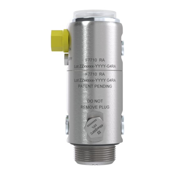
FIRE PROTECTION FLUID INDIRECT VALVE DOT CYLINDER
Brand:
Fike
| Category:
Safety Equipment
| Size: 6 MB
Table of Contents
Table of Contents
3
General Information
5
Introduction
5
How the System Operates
5
General Warning & Cautions
5
Extinguishing Agent
5
Extinguishing Mechanism
6
Limitations of 3M™ Novec™ 1230
6
Agent Exposure Information
6
Direct Clean Agent Systems
6
In Case of a Fire
7
Post Fire Instructions
7
System Description
8
Application Method
8
System Configurations
8
Single Nozzle Arrangement
8
Two Nozzle Arrangement
8
Three Nozzle Arrangement
8
Equipment Overview
9
Indirect Cylinder Valve
9
Lb [1.0Kg] Indirect Cylinder Assembly 4.12
10
Lb [2.0Kg] Indirect Cylinder Assembly 4.13
10
Lb [4.0Kg] Indirect Cylinder Assembly 4.14
11
Lb [6.0Kg] Indirect Cylinder Assembly
11
Lb [9.0Kg] Indirect Cylinder Assembly
12
Lb [14.0Kg] Indirect Cylinder Assembly
12
Lb [18.0Kg] Indirect Cylinder Assembly
13
Lb [1.0Kg] Cylinder Bracket
13
Lb [2.0Kg] Cylinder Bracket
14
13.2Lb [4.0 - 6.0Kg] Cylinder Bracket
14
Lb [9.0Kg] Cylinder Bracket
15
39.7Lb [14.0 & 18.0Kg] Cylinder Bracket
15
Discharge Nozzle
16
Component Bracket
16
Discharge Hose 3/8
17
Single & Dual Hose Clamps
17
Qr 3/8" Hose Fittings
18
Used with Bulkhead Connector
18
6/4Mm R80 Detection Tube
18
Qr Twinseal Fittings
19
End of Line (Eol)
19
Manual Actuator
20
Pressure Switch
20
Indirect Integrated Ball Valve Lock
21
Installation Accessories - Fasteners
21
Installation Fittings
21
P/N 06-959 - Nov 2023 - Rev B
22
Protective Coverings
22
System Labels
22
Operating -4°F to + 140°F
22
Caution Label
22
C to
22
System Signs
23
Figure 31
23
Part Number: See Table
23
Part Number Description
23
Design
24
Process Overview
24
Hazard Analysis
24
Temperature
24
Determine Agent Quantity
25
Nozzle Coverage & Location
28
Nozzle Quantity
30
System Parameters
30
Discharge Network Requirements
32
Flow Properties
32
Tee Configuration
32
Minimum Distance Surrounding a Tee
32
Tee Orientation
32
System Balancing
32
Lb [1.0Kg] - 1 Nozzle System Limitations
33
Port Configuration
33
Lb [2.0Kg] - 1 Nozzle System Limitations
33
Lb [4.0Kg] - 1 Nozzle System Limitations
34
Lb [6.0Kg] - 2 Nozzle System Limitations
34
Lb [9.0Kg] - 2 Nozzle System Limitations
35
Lb [14.0Kg] - 2 Nozzle System Limitations
35
Lb [18.0Kg] - 3 Nozzle System Limitations
36
Detection Tube Requirements
36
Shutdown Requirements
37
Accessories
37
Pressure Switches
37
Pressure Switch Wiring Information
38
Cable Connections
38
Installation
39
Placement Confirmation
39
Installation Overview
39
Cylinder Location & Bracket Installation
40
Discharge Nozzle & Bracket Installation
41
Discharge Hose Network Installation
42
Detection Tube Installation
43
End of Line or Manual Actuator Installation
44
Connection of the Detection Tube
45
Connection of the Discharge Hose Network
47
Commissioning of the System
48
Isolation Check
48
Gauge Removal
49
Important Note
50
Inspection
51
Leak Test on Detection Tube
51
Post-Commissioning Test
53
Warning Label
53
Monthly Inspections
53
Maintenance
54
Monthly Inspection
54
Month (Semiannual) - Service
54
Year - Service (Dot Stamped Cylinders)
55
Damaged or Corroded Cylinders
55
Cylinders Continuously in Service Without Discharge
55
Cylinder Retest
55
Year - Service (Hose Test)
56
Replacement
57
Commissioning Procedure
57
Post-Discharge Cleaning
57
Replacement Procedure
57
Manual Actuator Replacement Procedure
57
Application Guide
58
Cnc Machine
58
Revision Control
73
Advertisement
Advertisement
Related Products
Fike Categories
Security Sensors
Control Panel
Control Systems
Control Unit
Fire Alarms
More Fike Manuals
Login
Sign In
OR
Sign in with Facebook
Sign in with Google
Upload manual
Upload from disk
Upload from URL