
Subscribe to Our Youtube Channel
Summary of Contents for Fike 3M NOVEC 1230
- Page 1 INDIRECT SMALL SPACE SUPPRESSION SYSTEM 3M™ NOVEC™ 1230 FIRE PROTECTION FLUID INDIRECT VALVE DOT CYLINDER ASSEMBLY UL 2166 LISTED DOT DESIGN, INSTALLATION, OPERATION & MAINTENANCE MANUAL P/N 06-959 NOV 2023: REV B...
- Page 2 This manual is intended for use with the Fike Indirect Small Space Suppression System utilizing 3M™ Novec™ 1230 fire protection fluid. This manual is provided for those individuals that are responsible for the design, installation, operation, and maintenance of fire suppression systems used in compact environments.
-
Page 3: Table Of Contents
CONTENTS P/N 06-959 – NOV 2023 – REV B Page | 1 CONTENTS 3.28 SYSTEM SIGNS ............21 DESIGN ..............22 PROCESS OVERVIEW ..........22 GENERAL INFORMATION ......... 3 HAZARD ANALYSIS ..........22 DETERMINE AGENT QUANTITY ......23 INTRODUCTION ............3 HOW THE SYSTEM OPERATES ...... - Page 4 CONTENTS P/N 06-959 – NOV 2023 – REV B Page | 2 7.3.2 CYLINDERS CONTINUOUSLY IN SERVICE WITHOUT DISCHARGE .......... 53 7.3.3 CYLINDER RETEST ............ 53 5 YEAR – SERVICE (HOSE TEST) ......54 REPLACEMENT ........... 55 DE-COMMISSIONING PROCEDURE ....55 POST-DISCHARGE CLEANING ......
-
Page 5: General Information
EXTINGUISHING AGENT ball valve to control the communication with the detection tube. 3M Novec 1230 fluid is a fluorinated ketone stored as a liquid and discharged as a gas. It is electrically non- HOW THE SYSTEM OPERATES conductive and leaves no residue after discharge. -
Page 6: Extinguishing Mechanism
Saturated Vapor Density @ 68°F 0.08946 lb/ft AGENT EXPOSURE INFORMATION 3M Novec 1230 fluid is both low in acute toxicity and Specific volume of is a highly efficient clean agent extinguishant so that superheated vapor 0.00449 lb/ft it puts out fires long before the agent reaches a at 0.069psi [1.013... -
Page 7: In Case Of A Fire
Design, Installation, Operation, and Maintenance of the Direct 3M Novec 1230 system, please refer to manual 06-957. IN CASE OF A FIRE The system is designed to detect fires at an early stage; however, if an operator suspects a fire before... -
Page 8: System Description
20% safety factor in 10 seconds or less. The Single Nozzle arrangement can only be used in The Fike Indirect systems can be used, but are not the 2.2lb, 4.4lb & 8.8lb. [1.0kg, 2.0kg & 4.0kg] systems limited, to the protect the following: available in this manual. -
Page 9: Equipment Overview
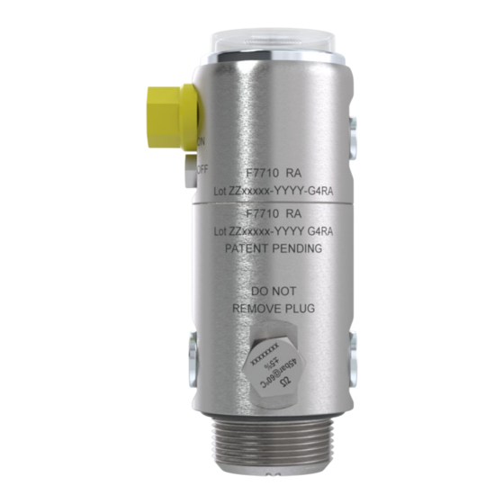
SECTION 3 – EQUIPMENT OVERVIEW P/N 06-959 – NOV 2023 – REV B Page | 7 3 EQUIPMENT OVERVIEW IMPORTANT NOTE: Any port not used in the final installation must be replaced with a permanent steel plug. INDIRECT CYLINDER VALVE The Indirect Valve is machined entirely of stainless steel. -
Page 10: Lb [1.0Kg] Indirect Cylinder Assembly 4.12
SECTION 3 – EQUIPMENT OVERVIEW P/N 06-959 – NOV 2023 – REV B Page | 8 2.2LB [1.0KG] INDIRECT CYLINDER ASSEMBLY 4.4LB [2.0KG] INDIRECT CYLINDER ASSEMBLY Part Number: See Table Part Number: See Table Part Number Description Part Number Description F-CTXDOT-014- 2.2lb [1.0kg] Indirect DOT F-CTXDOT-026-... -
Page 11: Lb [4.0Kg] Indirect Cylinder Assembly 4.14
SECTION 3 – EQUIPMENT OVERVIEW P/N 06-959 – NOV 2023 – REV B Page | 9 8.8LB [4.0KG] INDIRECT CYLINDER ASSEMBLY 13.2LB [6.0KG] INDIRECT CYLINDER ASSEMBLY Part Number: See Table Part Number: See Table Part Number Description Part Number Description F-CTXDOT-054- 8.8lb [4.0kg] Indirect DOT F-CTXDOT-075-... -
Page 12: Lb [9.0Kg] Indirect Cylinder Assembly
SECTION 3 – EQUIPMENT OVERVIEW P/N 06-959 – NOV 2023 – REV B Page | 10 19.8LB [9.0KG] INDIRECT CYLINDER ASSEMBLY 30.9LB [14.0KG] INDIRECT CYLINDER ASSEMBLY Part Number: See Table Part Number: See Table Part Number Description Part Number Description F-CTXDOT-120- 19.8lb [9.0kg] Indirect DOT F-CTXDOT-240-... -
Page 13: Lb [18.0Kg] Indirect Cylinder Assembly
SECTION 3 – EQUIPMENT OVERVIEW P/N 06-959 – NOV 2023 – REV B Page | 11 39.7LB [18.0KG] INDIRECT CYLINDER ASSEMBLY 2.2LB [1.0KG] CYLINDER BRACKET Part Number: See Table Part Number: F4068 Part Number Description The 2.2lb [1.0kg] cylinder bracket is specifically designed to allow quick and secure mounting of the F-CTXDOT-240- 39.7lb [18.0kg] Indirect DOT... -
Page 14: Lb [2.0Kg] Cylinder Bracket
SECTION 3 – EQUIPMENT OVERVIEW P/N 06-959 – NOV 2023 – REV B Page | 12 3.10 4.4LB [2.0KG] CYLINDER BRACKET 3.11 8.8 - 13.2LB [4.0 - 6.0KG] CYLINDER BRACKET Part Number: F4069 Part Number: F4075 The 4.4lb [2.0kg] cylinder bracket is specifically The 8.8 - 13.2lb [4.0 - 6.0kg] cylinder bracket is designed to allow quick and secure mounting of the specifically designed to allow quick and secure... -
Page 15: Lb [9.0Kg] Cylinder Bracket
SECTION 3 – EQUIPMENT OVERVIEW P/N 06-959 – NOV 2023 – REV B Page | 13 3.12 19.8LB [9.0KG] CYLINDER BRACKET 3.13 30.9 & 39.7LB [14.0 & 18.0KG] CYLINDER BRACKET Part Number: F4076 Part Number: F4037 The 19.8lb [9.0kg] cylinder bracket is specifically The 30.9 and 39.7lb [14.0 &... -
Page 16: Discharge Nozzle
SECTION 3 – EQUIPMENT OVERVIEW P/N 06-959 – NOV 2023 – REV B Page | 14 3.14 DISCHARGE NOZZLE 3.15 COMPONENT BRACKET Part Number: F7115 Part Number: F7234 The function of the clean agent discharge nozzle is to Component brackets are to be used to provide a control and distribute the agent throughout the secure fixing of the discharge nozzles and EOL protected risk area in a uniform, predetermined... -
Page 17: Discharge Hose 3/8
They are designed to provide the Body: Fire resistant optimized performance when used in conjunction Polyamide 6 Material with Fike Indirect Systems. The hoses are double- Cover Plate: Galvanised braided to endure high-impact conditions and Steel maintain discharge... -
Page 18: Qr 3/8" Hose Fittings
SECTION 3 – EQUIPMENT OVERVIEW P/N 06-959 – NOV 2023 – REV B Page | 16 3.19 6/4MM R80 DETECTION TUBE 3.18 QR 3/8” HOSE FITTINGS Part Number: See Table Part Number: See Table Part Number Description F7211-10 32.8ft [10 m] 6/4mm R80 Tube Part Description Number... -
Page 19: Qr Twinseal Fittings
SECTION 3 – EQUIPMENT OVERVIEW P/N 06-959 – NOV 2023 – REV B Page | 17 3.20 QR TWINSEAL FITTINGS 3.21 END OF LINE (EOL) Part Number: See Table Part Number: F7243-25 The End of Line (EOL) comes complete with a pressure Part Number Description gauge to allow for easy system status reporting. -
Page 20: Manual Actuator
N/O & N/C 261 psi [18 bar] F, Low (EOL). Pressure Switch The device is designed to be used with the Fike The pressure switch utilizes a diaphragm or piston, Detection Tube and is useful when line termination is depending on whether the pressure is falling or rising. -
Page 21: Indirect Integrated Ball Valve Lock
All anti-tamper locks have holes to allow a tamper- Fike offers a selection of fasteners to accommodate proof tag to be secured to it. The tamper-proof tags a safe and secure installation. It is important that the... -
Page 22: P/N 06-959 - Nov 2023 - Rev B
Fike Cylinder Inspection 02-17738 Record Tag To ensure the longevity of the system, Fike offers a range of protective coverings. The Twinseal fittings Labels are used to provide critical information and can be protected against the ingress of dust/dirt or allow for the safe upkeep of the system. -
Page 23: System Signs
CYLINDER INSPECTION RECORD TAG 3.28 SYSTEM SIGNS Part Number: See Table Part Number Description Fike Adhesive Caution Sign – 02-17005 Keep Door Closed, 13in x 10in Figure 34 [330mm x 254mm] DO NOT ENTER SIGN Fike Adhesive Caution Sign –... -
Page 24: Design
Class B Flammable Liquids and Flammable Before undertaking any design process, the person Gases responsible shall be trained by Fike and have a thorough understanding of the classification of fires Class C Energized Electrical Equipment and any applicable standards and regulations. -
Page 25: Determine Agent Quantity
B concentration, please reference the table below. system. Fike recommends that the minimum design concentration for Class B is 5.9%; therefore, any Step 5 - Determine Altitude Above Sea Level. value below 5.9% is not shown in the table. - Page 26 SECTION 4 – DESIGN P/N 06-959 – NOV 2023 – REV B Page | 24 Step 2 - Calculate Minimum Quantity of Agent Fuel To arrive at the minimum quantity of agent, please glycerine use the formula shown below, the minimum expected ambient temperature from the Hazard Analysis, and glycol ether DB the minimum design concentration from the previous...
- Page 27 0.8722 4.5% @ 70°F will be the Volume x 0.0407 = Agent in lbs. 0.6433 0.7185 0.8559 For clarity, Fike has only shown the typical minimum 0.6314 0.7053 0.8401 design concentrations used. Please contact Fike if you require any other values.
-
Page 28: Nozzle Coverage & Location
However, in many applications, there will be multiple nozzles. For Example: Although 3M Novec 1230 relies on a concentration to U.S. Units = 16lb @ 3937ft be effective, Fike recommends that the nozzles are 16 x 0.86 = 13.76lb [6.193kg]... - Page 29 Installations don’t always allow the nozzle to be placed tight to the ceiling, but Fike can allow 1.0ft It is important to locate nozzles so that the immediate [0.30m] distance from the base of the nozzle to the discharge profile of the nozzle is not impeded.
-
Page 30: Nozzle Quantity
All systems come with three discharge ports to allow for simple installation; however, the number of Fike allows a maximum of 2 cylinders to be connected discharge ports that can be utilized depends on the to a common detection tube. See Figure 39. Systems system size. - Page 31 Step 3 - Nozzle Discharge Summary The table below shows the agent per nozzle. Although Fike advise that all hazards are classed as unoccupied, hazards that have a final concentration of no more than 10% have a maximum exposure time...
-
Page 32: Discharge Network Requirements
The network is designed for harsh environments; however, care must be taken Fike has compiled a set of limitations to mitigate the when routing around the protected space to avoid separation and provide a homogenous delivery to sharp edges and sources of extreme heat. -
Page 33: Lb [1.0Kg] - 1 Nozzle System Limitations
SECTION 4 – DESIGN P/N 06-959 – NOV 2023 – REV B Page | 31 2.2LB [1.0KG] – 1 NOZZLE SYSTEM LIMITATIONS 4.4LB [2.0KG] – 1 NOZZLE SYSTEM LIMITATIONS For further details regarding the technical For further details regarding the technical information, please see the table below: information, please see the table below: Number of Nozzles... -
Page 34: Lb [4.0Kg] - 1 Nozzle System Limitations
SECTION 4 – DESIGN P/N 06-959 – NOV 2023 – REV B Page | 32 4.10 8.8LB [4.0KG] – 1 NOZZLE SYSTEM LIMITATIONS 4.11 13.2LB [6.0KG] – 2 NOZZLE SYSTEM LIMITATIONS For further details regarding the technical For further details regarding the technical information, please see the table below: information, please see the table below: Number of Nozzles... -
Page 35: Lb [9.0Kg] - 2 Nozzle System Limitations
SECTION 4 – DESIGN P/N 06-959 – NOV 2023 – REV B Page | 33 4.12 19.8LB [9.0KG] – 2 NOZZLE SYSTEM LIMITATIONS 4.13 30.9LB [14.0KG] – 2 NOZZLE SYSTEM LIMITATIONS For further details regarding the technical information, please see the table below: For further details regarding the technical information, please see the table below: Number of Nozzles... -
Page 36: Lb [18.0Kg] - 3 Nozzle System Limitations
4.14 39.7LB [18.0KG] – 3 NOZZLE SYSTEM LIMITATIONS 4.15 DETECTION TUBE REQUIREMENTS For further details regarding the technical The Fike Detection Tube is a heat-sensitive linear information, please see the table below: heat/flame detector. It is designed to burst at any location throughout its route where there is sufficient heat. -
Page 37: Shutdown Requirements
4.17.1 PRESSURE SWITCHES Fike offers its customers a factory setting of the switch point that is fixed and optimized to be used in conjunction with Fike products. Pressure switches are available with a 200mm, 3- Figure 54 core cable connection. -
Page 38: Pressure Switch Wiring Information
SECTION 4 – DESIGN P/N 06-959 – NOV 2023 – REV B Page | 36 Figure 56 TYPICAL F5013/F5014 INSTALLATION 4.17.2 PRESSURE SWITCH WIRING INFORMATION Normally Closed (N/C) Blue Normally Open (N/O) Brown 3. Common (COM) Black Intentionally left blank. Figure 57 CABLE CONNECTIONS IMPORTANT NOTE: All electrical connections... -
Page 39: Installation
The previous section of this manual will detail the Before the start of the installation of the Fike Indirect design process and identifying nozzle positions. It is system, you must have already identified: good to mark these out before fixing or drilling any... -
Page 40: Cylinder Location & Bracket Installation
SECTION 5 – INSTALLATION P/N 06-959 – NOV 2023 – REV B Page | 38 5.2 CYLINDER LOCATION & BRACKET INSTALLATION Vertical Only Figure 60 Figure 59 CYLINDER ORIENTATION TYPICAL CYLINDER BRACKET INSTALLATION Place cylinder into the bracket. Ensure the cylinder label and the serial number are visible. -
Page 41: Discharge Nozzle & Bracket Installation
SECTION 5 – INSTALLTION P/N 06-959 – NOV 2023 – REV B Page | 39 5.3 DISCHARGE NOZZLE & BRACKET INSTALLATION Having determined your nozzle position following the checks previously mentioned, secure the component bracket in place. Utilizing any of the approved nozzle connectors, secure the nozzle to the component bracket with the correct washers &... -
Page 42: Discharge Hose Network Installation
SECTION 5 – INSTALLATION P/N 06-959 – NOV 2023 – REV B Page | 40 5.4 DISCHARGE HOSE NETWORK INSTALLATION Connect the discharge hose to the bulkhead and connect finger tight only. See Figure 66. Utilizing 45° Elbow: - F6947 Figure 64 TYPICAL HOSE &... -
Page 43: Detection Tube Installation
Thoroughly clean the tube removing all dirt, grease, or grime. This will ensure a correct seal inside the fittings. Use only Fike supplied high- grade tube cutters Part Number F6410. This will minimize debris and ensure a clean and straight cut. -
Page 44: End Of Line Or Manual Actuator Installation
SECTION 5 – INSTALLATION P/N 06-959 – NOV 2023 – REV B Page | 42 5.6 END OF LINE OR MANUAL ACTUATOR INSTALLATION Figure 73 MOUNTING OF DEVICE Figure 72 For the EOL: remove the gauge and first set of locking nuts and washers, then insert the EOL into TYPICAL INSTALLATION OF EOL AND MANUAL ACTUATOR... -
Page 45: Connection Of The Detection Tube
SECTION 5 – INSTALLTION P/N 06-959 – NOV 2023 – REV B Page | 43 5.7 CONNECTION OF THE DETECTION TUBE If the section of the detection tube is outside your designated Detection area and subject to adverse conditions, cover the exposed section with the correct tube protection Part Number F6600, see Figure 77. - Page 46 Figure 83 INSERTING DETECTION TUBE TO VALVE IMPORTANT NOTE: Please check with Fike and 8. As the EOL comes complete with a QR Twinseal your Authority Having Jurisdiction before carrying Stud fitting, the connection can be made straight out multiple system connections.
-
Page 47: Connection Of The Discharge Hose Network
SECTION 5 – INSTALLTION P/N 06-959 – NOV 2023 – REV B Page | 45 CONNECTION OF THE DISCHARGE HOSE Insert adaptor Part Number F7400 to cylinder NETWORK port hand tight, further tighten with a spanner to the correct torque, see Figure 88. Figure 86 CONNECTION OF THE DISCHARGE HOSE Figure 88... -
Page 48: Commissioning Of The System
SECTION 5 – INSTALLATION P/N 06-959 – NOV 2023 – REV B Page | 46 CHECKS Check that both the charging adaptor, EOL, or Manual Actuator are clean and free from mechanical damage & corrosion. Check that you have the correct grade and sufficient quantity of Dry Nitrogen. -
Page 49: Gauge Removal
9. Detach the charging adaptor from the EOL or Manual Actuator in reverse order. There will be a 4. Screw-in the Fike Charging Adaptor clockwise by small audible pop associated with disconnecting hand until it bottoms out. See Figure 95. -
Page 50: Important Note
15-20-minute period. The information shown on the following page (SECTION 6 INSPECTION) details the actions required to carry out a full micro leak inspection using the Digital Leak Detection Kit from Fike. -
Page 51: Inspection
SECTION 6 – INSPECTION P/N 06-959 – NOV 2023 – REV B Page | 49 6 INSPECTION Connect the small length of tube and adaptor the gauge as shown, screwing in hand tight only. 6.1 LEAK TEST ON DETECTION TUBE Figure 103 CONNECTING THE ADAPTOR 3. - Page 52 SECTION 6 – INSPECTION P/N 06-959 – NOV 2023 – REV B Page | 50 8. Connect the male quick coupling to the adaptor IMPORTANT NOTE: Please note there can be and turn the charging adaptor ball valve to the small pressure fluctuations due to temperature open position.
-
Page 53: Post-Commissioning Test
Page | 51 6.2 POST-COMMISSIONING TEST 6.3 MONTHLY INSPECTIONS Before the Authorized Person installing the Fike 1. Visually check the hazard for changes that might system leaves the site take sufficient photos to reduce the efficiency of the system. This includes capture the installation. -
Page 54: Maintenance
SECTION 7 – MAINTENANCE P/N 06-959 – NOV 2023 – REV B Page | 52 7 MAINTENANCE Accurate and regular maintenance in accordance with this manual will ensure the system will operate effectively and safely throughout its lifetime. Installation or removal of this fire suppression system shall only be performed by an authorized person with a valid manufacturer’s training certificate. -
Page 55: Year - Service (Dot Stamped Cylinders)
SECTION 7 - MAINTENANCE P/N 06-959 – NOV 2023 – REV B Page | 53 5 YEAR - SERVICE (DOT STAMPED CYLINDERS) 12 Verify the weight of the agent in each container using a certified scale, ensuring it matches the Depending on your system's status and condition, agent weight on the label. -
Page 56: Year - Service (Hose Test)
“E” Pamphlet C-6, Section 3 Table 2 RETEST SCHEDULE IMPORTANT NOTE: Fike advises that the Indirect valve be rebuilt or replaced following a hydrostatic Intentionally left blank. test. 5 YEAR – SERVICE (HOSE TEST) Test or replace all 3/8” discharge hoses. The test shall be in accordance with the requirements of NFPA 2001. -
Page 57: Replacement
Unscrew Part B anticlockwise with a 6mm hex transport vehicle or bracket. wrench and replace it with a new item, Part Return the empty cylinder to Fike for recharge or Number F7254 replace with like cylinder. 3. Screw back in Part A... -
Page 58: Application Guide
SECTION 9 – APPLICATION GUIDE P/N 06-959 – NOV 2023 – REV B Page | 56 9 APPLICATION GUIDE 9.1 CNC MACHINE Design Concentration 5.9% Fire Classification Class B Agent Required 7.7 lb [3.5kg] 7.22 x 3.93 x 4.92ft L x W X H [2.20 x 1.20 x 1.50m] System Size 8.8lb [4.0kg]... - Page 59 QR TWINSEAL FITTINGS 25 bar End of the Line (EOL): QR Twinseal Stud: 1/8'' F7243-25 F7041 6/4mm Tube Threaded – 6/4mm Tube F7270-25 25 bar Fike Manual Actuator QR Twinseal Swl Elbow: 1/8'' F7014 Threaded - 6/4mm Tube F7254 Replacement Diaphragm...
- Page 60 Activation Label 77 x210 02-17738 Cylinder Inspection Tag INSTALLATION ACCESSORIES – SIGNS 02-17005 Fike Adhesive Caution Sign – Keep Door Closed, 13in x 10in [330mm x 254mm] 02-17006 Fike Adhesive Caution Sign – Do Not Enter, 9in x 6in [229mm...
- Page 61 SECTION 11 – APPENDIX 2 P/N 06-959 – NOV 2023 – REV B Page | 59 APPENDIX 2 Aluminum Hydroxide Alum Potassium Sulfate (Alum), 10% DETECTION TUBING CHEMICAL RESISTANCE TABLE Alum Potassium Sulfate (Alum), 100% Aluminum Sulfate Ratings Chemical Effect Amines A: No effect - Excellent Ammonia 10%...
- Page 62 SECTION 11 – APPENDIX 2 P/N 06-959 – NOV 2023 – REV B Page | 60 Beef Sugar Liquids Glycerine Benzaldehyde Cycolic Acid Benzene Gold Monocyanide Cotton Seed Benzoic Acid Cresote Benzol Diesel Fuel (2D to 5D) Borax (Sodium Borate) Potassium Ferrocyanide Boric Acid Potassium Hydroxide (50%)
- Page 63 SECTION 12 – APPENDIX 3 P/N 06-957 – NOV 2023 – REV B Page | 61 12 APPENDIX 3...
- Page 64 SECTION 12 - APPENDIX 3 P/N 06-957 - NOV 2023 – REV B Page | 62...
- Page 65 SECTION 12 – APPENDIX 3 P/N 06-957 – NOV 2023 – REV B Page | 63...
- Page 66 SECTION 12 - APPENDIX 3 P/N 06-957 - NOV 2023 – REV B Page | 64...
- Page 67 SECTION 12 – APPENDIX 3 P/N 06-957 – NOV 2023 – REV B Page | 65...
- Page 68 SECTION 12 - APPENDIX 3 P/N 06-957 - NOV 2023 – REV B Page | 66...
- Page 69 SECTION 12 – APPENDIX 3 P/N 06-957 – NOV 2023 – REV B Page | 67...
- Page 70 SECTION 12 - APPENDIX 3 P/N 06-957 - NOV 2023 – REV B Page | 68...
- Page 71 SECTION 12 – APPENDIX 3 P/N 06-957 – NOV 2023 – REV B Page | 69...
- Page 72 SECTION 12 - APPENDIX 3 P/N 06-957 - NOV 2023 – REV B Page | 70 Intentionally left blank.
-
Page 73: Revision Control
SECTION 13 – REVISION CONTROL P/N 06-959 – NOV 2023 – REV B Page | 71 13 REVISION CONTROL ISSUE MAIN ISSUE MAIN REVISION REVISION DATE CHANGES/REASON DATE CHANGES/REASON Edition and initial 12/2022 version 05/2023 Received UL Approval 08/2023 UL Listed Version... - Page 74 MANUFACTURER DISTRIBUTOR 704 SW 10 Street Blue Springs, Missouri 64015 Main: +001 816-229-3405 Toll-Free: 1-800-YES-Fike (937-3453) Monday through Friday 8 AM to 4:30 PM US central time www.Fike.com...
Need help?
Do you have a question about the 3M NOVEC 1230 and is the answer not in the manual?
Questions and answers