Sign In
Upload
Manuals
Brands
FAST ComTec Manuals
Measuring Instruments
MCA4A
FAST ComTec MCA4A Multichannel Analyzer Manuals
Manuals and User Guides for FAST ComTec MCA4A Multichannel Analyzer. We have
1
FAST ComTec MCA4A Multichannel Analyzer manual available for free PDF download: User Manual
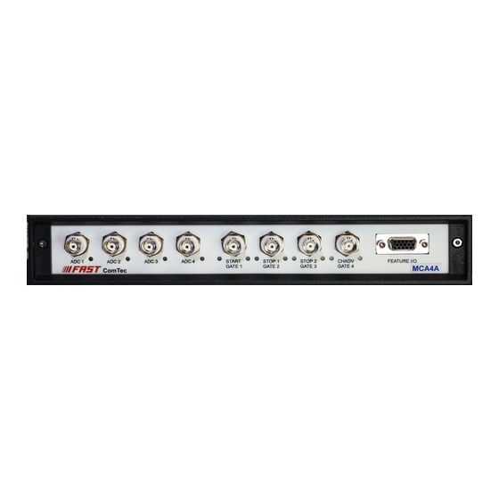
FAST ComTec MCA4A User Manual (107 pages)
4 Input Multichannel Analyzer 2 Input Multichannel Scaler
Brand:
FAST ComTec
| Category:
Measuring Instruments
| Size: 4.97 MB
Table of Contents
Table of Contents
4
1 Introduction
9
2 Installation Procedure
10
Hard- and Software Requirements
10
Driver Installation
11
Fig. 2.1: Device Manager
11
Fig. 2.2: Driver Installation
11
Fig. 2.3: Choosing the Right Folder
12
Fig. 2.4: Device Manager after Successful Driver Installation
12
Software Installation
13
Hardware Installation
13
Fig. 2.5: MCA4A Rear Panel
13
Getting Started
14
Initial Offset Calibration
14
Fig. 2.6: Software Startup Screen
14
Fig. 2.7: MCA4A Settings Window
14
Fig. 2.8: ADC Settings Dialog (2X)
15
Basic Scope Measurement
16
Fig. 2.9: ADC Settings for the First Measurement
16
Fig. 2.10: Scale Parameters for the Scope Display
17
Fig. 2.11: Scale Parameters for the Spectrum Display
17
Fig. 2.12: 1St Scope Measurement
18
Fig. 2.13: Single Display Options Dialog
18
Simple Pulse Height Analysis
19
Fig. 2.14: Setup a FFT Analysis
19
Fig. 2.15: FFT Analysis Display
19
Fig. 2.16: Setup a Gaussian Fit PHA Measurement
20
Fig. 2.17: Scope Picture of a 1Mhz Sine Wave
20
Fig. 2.18: Switch to Firmware Based PHA
21
Measuring a Typical Pre-Amplifier Signal
22
Fig. 2.19: Setup the Internal Test Pulser
22
Fig. 2.20: Setup the Internal Test Pulser
23
Fig. 2.21: Scope Picture of the Original Test Pulser Signals
23
Fig. 2.22: Scope Picture of the Internal Test Pulser
24
Fig. 2.23: Scope Picture of the Inverted and Positive Going Test Pulser Signals
24
Fig. 2.24: Enable the Trapezoidal Filter
25
Fig. 2.25: Effects of Different Pole Zero Settings
25
Fig. 2.26: Scope Picture of the Trapezoidal Shaped Test Pulser Signals
25
Multiscaling Measurement
26
Fig. 2.27: Modified Shaper Parameters
26
Fig. 2.28: MCA4 Settings: Select MCS Mode
26
Fig. 2.29: MCS Settings for a Simple Measurement
27
Fig. 2.30: Simple MCS Spectrum
27
Basic Usage of the Realtimeclock Option
28
Fig. 2.31: Basic RTC Experiment
28
Fig. 2.32: Triggering the RTC with the TRG Signal
28
Installing more than One MCA4A Module
29
Fig. 2.33: Basic Time Spectra
29
Fig. 2.34: RTC Spectrum Definition
29
Fig. 2.35: Editing MCA4.INI
30
3 Hardware Description
31
Overview
31
Front Panel Connectors
31
Analog ADC Inputs
31
Fig. 3.1: MCA4 Front Panel
31
Changing the Input Range
32
Fig. 3.2: Left: Jumper Setting for Different Input Ranges, Right: Jumper Positions
32
Fig. 3.3: Simplified Analog Input and ADC Circuitry
32
GATE / MCS Inputs
33
Fig. 3.4: Circuit Diagram of each GATE / MCS Input
33
FEATURE I/O Connector
34
Fig. 3.5: Circuit Diagram of the FEATURE I/O Port
34
MCA Section, Analog-To-Digital Converter
35
Scope Mode
35
Fig. 3.6: Digital I/O Port Details
35
Fig. 3.7: GO-LINE Details
35
Pulse Height Analysis
36
Fig. 3.8: Pulsewidth Check - Discard "False" Pulses
36
Fig. 3.9: Gaussian Shaped Pulse Fitting
37
Fig. 3.10: Flattop Pulse Fitting Modes
37
Sampled Voltage Analysis
38
Single Channel Analyzer (SCA)
38
Real Time, Live Time and System Time Counter
38
List Mode Data Acquisition
38
Event Tagging, Spectrum Multiscaling
38
Fig. 3.11: Pile-Up Detection
38
Multichannel Scaler
39
Introduction
39
Dwell Time
39
Sweep Counter
39
Spectrum Sequencing
39
Octal 125 Mhz Counter / Timer
40
Time Base / Reference Clock
40
Fig. 3.12: Octal 125 Mhz Counter Connector
40
4 Software Description
41
Server Functions
41
Initialization Files
41
Fig. 4.1: MCA4 Server Window
41
Action Menus
42
File Menu
42
Fig. 4.2: Mca4.Ini File
42
Fig. 4.3: Data Operations Dialog for MPA Data (Left) and Selected Spectra (Right)
43
Fig. 4.4: Replay Settings Dialog
43
Settings Overview
44
Fig. 4.5: about MCA4 Dialog Box and Installed Items
44
Fig. 4.6: Settings Overview, Left: PHA Mode, Right: MCS Mode, more than One MCA4 Module
44
MCS Settings
45
Fig. 4.7: MCS Settings for One (Left) or Two Stop Inputs (Right)
45
Presets
46
Fig. 4.8: Thresholds Dialog
46
Fig. 4.9: ADC Presets Dialog
46
ADC Settings
47
Fig. 4.10: ADC Settings Dialog, Right: Scope Mode
47
Fig. 4.11: Left: Setting Tag Bits, Right: Advanced Settings
49
Fig. 4.12: Setting a ROI in the Waveform for the Pulse-Height Analysis of Flattop Pulses
50
Fig. 4.13: How to Switch off Auto Scaling
50
Fig. 4.14: Setting Parameters for Flattop PHA
50
Pulse-Width Histogramming
51
Fig. 4.15: Pulse Width Histogramming
51
Scaler Setting
52
Fig. 4.16 Scaler Settings Dialog Box
52
Fig. 4.17 Left: MCA4-Scaler Status Utility, Right: as Ratemeter
52
System Definition
53
Fig. 4.18: System Definition Dialog Box
53
Calculated Spectra Dialog
54
Fig. 4.19: Dual Parameter and Calculated Spectra Dialog Box
54
Fig. 4.20: Multi Display Setting
54
Fig. 4.21: Multi Time Display Setting, Left with Installed RTC Option and Right Without RTC Option
55
Fig. 4.22: Calculated Spectrum Setting, with (Left) and Without (Right) RTC and Coincidence Options
56
Fig. 4.23: Sum of Counts Dialog
56
Fig. 4.24: Sum of Counts Spectrum before and after Calibration
57
Conditions
58
Fig. 4.25: Conditions
58
Fig. 4.26: ROI Conditions Dialog
58
Fig. 4.27: Combine Conditions Dialog
58
Fig. 4.28: Conditions Dialog with Tag Bits Enabled
59
Fig. 4.29: Tag Conditions Dialog
59
File Formats
60
Control Language
62
Controlling the MCA4 Windows Server Via DDE
68
Open Conversation
68
DDE Execute
68
Fig. 4.30: Opening the DDE Conversation with the MCA4 Server in Labview
68
Fig. 4.31: Executing a MCA4 Command from a Labview Application
69
Fig. 4.32: Getting the Total Number of Spectrum Data with Labview
69
Close Conversation
70
Fig. 4.33: Getting the Data with Labview
70
Fig. 4.34: Closing the DDE Communication in Labview
70
Fig. 4.35: Control Panel of the Demo VI for Labview
71
Controlling the MCA4 Windows Server Via DLL
72
5 MPANT Software
73
Fig. 5.1: MPANT Main Window
73
File Menu
74
Fig. 5.2: MPANT Map and Isometric Display
74
Fig. 5.3: File New Display Dialog
75
Fig. 5.4: Compare Dialog
76
Fig. 5.5: Compare Two Spectra
76
Window Menu
77
Fig. 5.6: Print Dialog
77
Region Menu
78
Fig. 5.7: Slice and Rectangular ROI Editing Dialog
80
Fig. 5.8: Polygonal ROI Editing Dialog
80
Fig. 5.9: Single Gaussian Peak Fit
81
Fig. 5.10: Evaluation of a Non-Gaussian Peak
82
Fig. 5.11: Log File Options
82
Options Menu
84
Fig. 5.12: Colors Dialog
84
Fig. 5.13: Color Palette Dialog
84
Fig. 5.14: Single Display Options Dialog
85
Fig. 5.15: Map Display Options Dialog
86
Fig. 5.16: Isometric Display Options Dialog
86
Fig. 5.17: Axis Parameters Dialog
87
Fig. 5.18: Scale Parameters Dialog
88
Fig. 5.19: Calibration Dialog
89
Fig. 5.20: Comments Dialog
90
Fig. 5.21: Settings Dialog
91
Fig. 5.22: Data Operations Dialog
91
Fig. 5.23: System Definition Dialog
92
Fig. 5.24: Spectra Dialog
92
Fig. 5.25: Slice Dialog
93
Fig. 5.26: Replay Dialog
93
Fig. 5.27: Tool Bar Dialog
94
Fig. 5.28: Function Keys Dialog
94
Action Menus
95
Fig. 5.29: MPANT with Four Systems Enabled
96
6 Programming and Software Options
97
7 Appendix
98
Absolute Maximum Ratings
98
Recommended Operating Conditions
98
Specifications
98
ADC Inputs
98
GATE / MCS Inputs
98
SCA Outputs
99
Digital I/O Ports
99
Reference Clock I/O
99
Octal Counter Inputs
99
RTC RESET Input
99
Performance
100
General
100
Analog-To-Digital Converter
100
Fig. 7.1: ADC Noise Spectrum (Generated with a Ramp Generator and Gaussian Fit)
101
Fig. 7.2: ADC Integral Linearity Plot for 32K ADC Range
101
Fig. 7.3: ADC Differential Non-Linearity Plot for 32K ADC Range
101
Fig. 7.4: ADC DNL Distribution
101
Counters
102
Multichannel Scaler
102
Fig. 7.5: Typical Peak Widths of Gaussian Fitted Pulses (32K Range, 4Μs Shaping)
102
Fig. 7.6: MCS Noise Spectrum (32K Range, 50Ns Dwelltime)
103
Fig. 7.7: MCS Differential Non-Linearity Plot (32K Range, 50Ns Dwelltime)
103
Physical
104
Accessories
104
Optional
104
Fig. 7.8: MCS DNL Distribution
104
Trouble Shooting
105
Fig. 7.9: Counter Cable BNC or Lemo
105
Personal Notes
107
Advertisement
Advertisement
Related Products
FAST ComTec MCDWIN
FAST ComTec MPA4
FAST ComTec MCCD
FAST ComTec Categories
Amplifier
Computer Hardware
Network Hardware
Media Converter
Pulse Generator
More FAST ComTec Manuals
Login
Sign In
OR
Sign in with Facebook
Sign in with Google
Upload manual
Upload from disk
Upload from URL