Sign In
Upload
Manuals
Brands
Fantic Motor Manuals
Motorcycle
TL 250
Fantic Motor TL 250 Manuals
Manuals and User Guides for Fantic Motor TL 250. We have
1
Fantic Motor TL 250 manual available for free PDF download: Workshop Manual
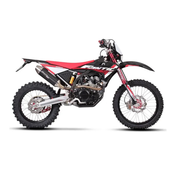
Fantic Motor TL 250 Workshop Manual (138 pages)
Brand:
Fantic Motor
| Category:
Motorcycle
| Size: 24 MB
Table of Contents
Table of Contents
4
Safety Rules
8
Maintenance Rules
12
Maintenance
12
Preparation Prior to Work
12
Torque Settings
13
Vehicle Identification
14
Spare Parts
15
Bodywork Removal
16
Removing the Seat
16
Removing the Rear Fender
16
Removing the Radiator Shrouds
17
Removing the Fuel Tank
17
Removing the Headlight Assembly
17
Removing the Mud Flap
18
Removing the Front Mudguard
18
Removing the Licence Plate Bracket
18
Removing the Rear Subframe
19
Removing the Kickstand
19
Removing the Swingarm Pivot Bolt
19
Dashboard
20
Dashboard TL 250 Carburettor Koso Db Ex-O2
20
Replacing the Battery
20
Dashboard Functions
20
How to Use the Adjust Button
20
How to Use the Select Button
21
How to Use the Adjust + Select X 3 Button
22
Tyre Detection Point Setup
23
Clock Setup
23
Dashboard Koso Db-01Rn
25
Air Filter Removal
31
Light Bulb Changing
32
Changing the Headlight Bulb on the Carburettor Model
32
Changing Direction Indicator Light Bulbs
32
Disassembling the Forks
33
Casa Competizione Fork TL 250 Carburettor and Injection
33
Casa Performance Fork TL 250 Carburettor
33
Changing Fork Oil
34
Disassembling the Fork Legs
34
Braking System
35
Front Brake
35
Rear Brake
35
Replacing the Brake Pads
36
Front Brake
36
Rear Brake
36
Front Oil Level
37
Rear Oil Level
37
Bleeding the Front Brake
37
Bleeding the Rear Brake
37
Adjusting the Brakes
38
Front Brake
38
Rear Brake
38
Adjusting the Clutch
38
Checking and Adjusting Steering Play
39
Chain Tensioning
39
Headlight Beam
40
Carburettor
40
Idling (Adjusting Idling Speed)
40
Removing the Engine from the Frame
41
Engine Maintenance
44
Engine Specifications
44
Vehicle Operation and Maintenance on Carburettor Version
45
Section 5 Cooling System Troubleshooting
47
Electrical Devices
48
Location of Fuses
48
Notes on the Battery
48
Wiring Diagram - TL 250 4-Stroke 2016
50
Wiring Diagram - TL Injection 250 Euro4 2018
52
OBD Connectors
55
Ecu
56
Fuel Injector
56
Fuses and Relays
58
Stepper Motor
59
Lights Contactor
60
Radiator Fan Contactor
60
Lambda Sensor
61
Fuses and Relays
62
Battery
63
Replacing the Battery
63
Notes on the Battery
63
Diagnostic Port and Instrument Connection
64
Removing the Fuel Tank
65
Removing the Electronic Injection
67
Removing the Injector
67
Removing the Throttle Body
68
Removing the MAP Sensor
69
Error Code
70
Ignition Module Error Code Table
70
ABS Module Error Code Tablem
90
Troubleshooting
92
Bike Doesn't Start/Starting Difficulty
92
Fuel System Carburettor Version
92
Poor Performance at MID Range and High Speed
94
Overheating or Excessive Cooling
95
Defective Braking/Poor Braking
95
Front Fork Malfunctioning
96
Steering Instability
96
Starter Motor Not Working
97
Faulty Indicator System and Lighting
97
DIM Headlight
97
Blown Bulb
97
Direction Indicators Not Flashing
97
Direction Indicators Stay on
98
Direction Indicators Flashing too Slow
98
Direction Indicators Flashing too Fast
98
Horn Does Not Work
98
Products
99
Engine
100
Removing the Engine Fully
100
Changing Engine Oil and Engine Oil Filters
102
Engine Oil Level
103
Cylinder Head and Valve
104
Remove the Cylinder Head Cover
104
Remove the Cylinder Head
105
Cylinder Head Cover Disassembly
105
Disassemble the Cylinder Head
105
Inspect the Valve and Valve Spring
106
Inspect the Rocker Arm and Rocker Arm Shaft
106
Inspect the Camshaft Parts
107
Inspect the Cylinder Head
107
Inspect and Lap the Valve Seat
107
Inspect the Valve Guide
107
Measure the Width of the Valve Seating Surface
108
Assemble the Cylinder Head
108
Assemble the Cylinder Head Cover
109
Install the Cylinder Head
109
Adjusting Timing
110
Install the Cylinder Head Cover
110
Checking and Adjusting Tappets
111
Cylinder and Piston
112
Remove the Cylinder
112
Inspect the Cylinder Block
112
Remove the Piston
112
Inspecting the Piston and Rings
113
Install the Piston Rings
114
Install the Piston
115
Install the Cylinder Block
115
Clutch, Drive Gear, Freewheel, Oil Pump and Gearshift
115
Remove the Crankcase Cover on the Engine's Right-Hand Side
115
Remove the Water Pump Shaft, the Water Seal Assembly and the Oil Seal
115
Remove the Clutch
116
Remove the Drive Gear, Freewheel and Starter Gear
116
Remove the Oil Pump on the Right Side
116
Remove the Step Gear
116
Remove the Starter Motor
117
Remove the Gearshift
117
Inspect the Crankcase Cover on the Right Side
117
Inspect the Water Pump Shaft, Impeller, Water Seal Assembly and Oil Seal
117
Inspect the Starter Shaft
118
Inspect the Clutch Spring
118
Inspect the Clutch Disc
119
Inspect the Clutch Basket
119
Inspect the Drive Gear
120
Inspect the Freewheel
120
Inspect the Primary Starter Gear
120
Inspect the Oil Pump on the Right Side of the Engine Case
120
Inspect the Starter Motor and Step Gear
121
Inspect the Gearshift
121
Assemble the Kickstarter Spindle
121
Assemble the Step Gear
121
Assemble the Gearshift
121
Assemble the Oil Pump on the Right Side of the Engine Case
121
Assemble the Freewheel
121
Install the Primary Gear and Freewheel
121
Install the Drive Gear
122
Install the Clutch
122
Assemble the Starter Motor
122
Install the Crankcase Cover on the Right Side
122
Generator, Crankshaft Balancing and Driven Gear
123
Remove the Crankcase Cover on the Left Side
123
Remove the Generator Stator
123
Remove the Generator Rotor
123
Remove the Balancer Drive Gear and Driven Gear
124
Remove the Oil Pump on the Left Side
124
Inspect the Crankcase Cover on the Left Side
124
Inspect the Generator Rotor and Stator
124
Inspect the Balancer Drive Gear and Driven Gear
124
Inspect the Left Side Oil Pump
125
Install the Left Side Oil Pump
125
Install the Balancer Drive Gear and Driven Gear
125
Install the Generator Rotor
125
Install the Generator Stator
126
Install the Crankcase Cover on the Left Side
126
Crankcase, Crankshaft, Gearbox and Balancer Shaft
126
Removing the Crankcase
126
Remove the Crankshaft, Balancer Shaft, Mainshaft and Countershaft
126
Inspect the Crankshaft
126
Inspect the Shift Fork, Fork Shaft and Shift Drum
126
Inspect the Bearings on the Crankcase Left and Right Sides
127
Inspect the Mainshaft Assembly and Countershaft Assembly
128
Inspect the Oil Filters and Their Components
129
Assemble the Gearbox, Crankshaft and Balancer Shaft
129
Assemble the Left and Right Crankcase Halves and the Filter
129
Injection Maintenance Chart
131
Carburettor Mainteinance Chart
134
Advertisement
Advertisement
Related Products
Fantic Motor TZ 125 2011
Fantic Motor TZ 250 2011
Fantic Motor TZ 300 2011
Fantic Motor TF 250 2012
Fantic Motor TX1
Fantic Motor TX2
Fantic Motor 125 Series
Fantic Motor Caballero 50
Fantic Motor Caballero 500 2021
Fantic Motor Enduro 125 Casa
Fantic Motor Categories
Motorcycle
Scooter
Bicycle
Engine
More Fantic Motor Manuals
Login
Sign In
OR
Sign in with Facebook
Sign in with Google
Upload manual
Upload from disk
Upload from URL