Sign In
Upload
Manuals
Brands
FangLing Manuals
Cutter
F2500T(A/B)
FangLing F2500T(A/B) Control System Manuals
Manuals and User Guides for FangLing F2500T(A/B) Control System. We have
1
FangLing F2500T(A/B) Control System manual available for free PDF download: Operation And Installation Manual
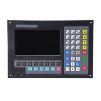
FangLing F2500T(A/B) Operation And Installation Manual (147 pages)
Shape Cutting Control System
Brand:
FangLing
| Category:
Cutter
| Size: 3 MB
Table of Contents
Read this Manual
3
Table of Contents
5
Chapter 1 F2000 Series Control System Introduction
10
System Brief Introduction
10
F2100B/T System
10
F2200 B/T System
11
F2300A/B/T (A)/(B) System
11
F2500A/B/T (A)/ (B) System
12
F2600/T System
12
Characteristics of System
13
Technical Indicator
14
System Interface
15
Hardware Configuration
15
F2100 B/T Hardware Configuration
15
F2200 B/T Hardware Configuration
15
F2300 A/B/T Hardware Configuration
16
F2500 A/B/T Hardware Configuration
16
F2600/T Hardware Configuration
16
Chapter 2 Starting up of System
18
Introduction of System Operation Board
18
Power on Processing and Main Interface
20
Function Index of Main Interface
22
Chapter 3 Cutting Function
23
Cutting Operation Index
25
Speed Regulation
26
Normal Speed Regulation
26
Quick Speed Regulation
26
Forward
26
Backward
27
Edge Cutting / Offset Cutting / Return
27
Back to Reference Function
29
Oxygen Gas Preheat Time Regulation
30
Perforation Point Selection
30
Dynamic Amplification
32
Cutting Exit
32
Frame
33
Arc Thc Instruction ( Typical of the "T" in F2000 Series Cnc System )
33
Wiring Instruction
33
Arc Setting and Actual Arc Displaying
35
Location Check
35
Set Arc / Adjust Arc While Running
36
Auto / Manual Turn High
36
Crash / Position Successful Signal Check
37
Chapter 4 Part Option
38
Xy Mirror
38
Start Point Selection
38
Angle Adjustment
40
Steel Plate Adjustment
40
Steel Plate Adjust Angle Memory Function
41
Enter Angle
41
Array
42
Zoom In/Out
45
Select Row/Number
46
Select Row
46
Select Number
47
Operation after Select Row/Number
47
Restore
48
Chapter 5 Manual Function
49
Fixed Moving Function
49
Continuous Moving Function
50
Fixed-Length Moving Function
50
Breakpoint Recovery
50
Chapter 6 File Operation
52
Files in the Hard Disk
52
Files in Theu Disk
53
Search File
55
Edit Code
55
New File
56
Compile Code
56
Folder Manager
56
Select Work Folder
56
New Folder
57
Clear File
58
Chapter 7 Parameter Setting
59
Common Parameters
59
Flame Parameters
60
Plasma Parameters
63
Powder Parameters
65
System Parameters
66
Parameter Import
68
Parameter Export
69
Save Parameters
70
Chapter 8 Diagnosis Function
71
Diagnosis Interface Index
72
Input Diagnosis
72
Output Diagnosis
73
Keyboard Diagnosis
73
System Self-Check
74
Date and Time
75
System Definition
76
Parameter Backup and Restore
76
Input Definition
76
Output Definition
77
Coordinate Definition
78
Motor
80
Remote Controller
81
Default Coordinate
81
Default IJ Coordinate
81
Option
81
Switch between Metric and Inches
82
Short Line Fitting
82
Steel Plate Angle Memory
82
F Instruction Forbidden
82
Manual Angle Input to Adjust Steel Plate
82
Language Switch
82
Add a Language File
83
Clear File
83
System Update
83
Chapter 9 Graph Management
85
Choose Graph
85
Film/Hole Size
86
Chapter 10 Code Explanation
88
Code Symbol and Interpretation
88
Coordinate System
88
G Code Explanation
89
M Code Explanation
95
Chapter 11 Port Explanation
97
Input Port
97
Input Wiring Instructions
99
Remote Controller Input
100
Output Port
101
Output Wiring Instructions
103
Oxygen Gas Typical Connection
103
Three Level Perforation Circuit
104
Typical Circuit of Using Powder
105
Typical Circuit of Using Plasma Cutting
106
Motor Port
108
Typical Wiring Diagram of the Motor Interfaces
109
Connection Methods for Differential Stepper Driver
109
Com-Anode Connection Methods for Stepper Driver
110
Connection Methods of Servo Driver of Panasonic Company
111
Arc THC Module Interface (THC)
112
DC MOTOR Interface Instruction
112
Arc Import Instruction
113
Position Interface (PS) Instruction
114
Arcing Interface (ARC_START) Instruction
114
Wiring Diagram of F2100T CNC System with Arc THC Module
115
Wiring Diagram of Double Approach Switch
116
Power Input Instruction
116
Chapter 12 Use of Bios
117
System Upgrade
118
Welcome Interface Upgrade
118
Movement Control Upgrade
118
System Backup
118
System Reset
119
Chapter 13 Installation and Debugging
120
Horizontal / Vertical Pulses Number Setting
120
Chapter 14 Shanghai Fangling F1500 Remote Controller
122
Wireless Remote Control Module Performance and Characteristic
122
The Layout of Remote Controller
123
The Output Port of Receiver
123
Interpretation of Jumper Switch
124
Wiring Connection Figure of F1500 and Fang Ling Numerical Control System
126
Appendix 1 G、M Code Rapid Consult
127
A2.1 Flame Cutting Timing Sequence
128
Appendix 2 Io Timing Sequence Figure of F2000 Series Numerical Control System
128
A2.2 Plasma Io Timing Sequence
130
Appendix 3 Interpretation of Wiring Connection between F2000 Series and Common Thc
132
A3.1 Connection with F1620/F1630 Thc
132
A3.2 Connection with Hyd Thc
134
A3.3 Connection with Sh-Hc30 Thc
136
A3.4 Connection with Ontime Thc
138
A3.5 Connection with Pthc-2
139
Appendix 4 Interpretation of F2000 Full Series System Install Size
141
A4.1 F2100B/T Profile Install Size
141
A4.2 F2200B/T Profile Install Size
141
A4.3 F2300A/B/T Profile Install Size
142
A4.4 F2500A/B/T Profile Install Size
143
A4.5 F2600/T Profile Install Size
144
Contact Information
145
Shanghai Office
145
Shijiazhuang Office
147
Advertisement
Advertisement
Related Products
FangLing F2500(A/B)
FangLing F2100B/T
FangLing F2300(A/B)
FangLing F2200B/T
FangLing F2600T
FangLing F2300T(A/B)
FangLing Categories
Cutter
More FangLing Manuals
Login
Sign In
OR
Sign in with Facebook
Sign in with Google
Upload manual
Upload from disk
Upload from URL