Sign In
Upload
Manuals
Brands
Eurotherm Manuals
DC Drives
590A SERIES
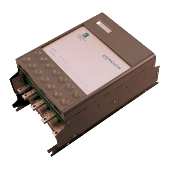
User Manuals: Eurotherm 590A SERIES DC Drive Control
Manuals and User Guides for Eurotherm 590A SERIES DC Drive Control. We have
1
Eurotherm 590A SERIES DC Drive Control manual available for free PDF download: Product Manual
Eurotherm 590A SERIES Product Manual (110 pages)
THREE PHASE CONVERTORS
Brand:
Eurotherm
| Category:
DC Drives
| Size: 4 MB
Table of Contents
Warnings and Instructions
3
Protective Insulation
4
Table of Contents
5
1 Introduction
6
545/590A Upgrade
6
To 590A Conversion Chart
7
Introduction
9
2 Technical Specifications
10
Control
10
Power
11
Output Ratings
12
Armature Ratings
12
Mechanical Details
13
Field Rating
13
3 Product Code
15
4 Installation & Wiring
16
Installation
16
Ventilation and Cooling
16
Basic Wiring Instructions
16
European Style Fuses
16
Dimensions
18
Notes on Wiring
20
Electrical Rating
21
Field Terminal Kits Available for Power Cable Connection
21
Motor Overload
21
Additional Installation Requirements for UL508
21
Diagrams
22
EMC Installation Guidelines
34
EMC Filters to Reduce Line Conducted Noise
34
Filter Mounting Details
35
Interaction with Earth-Fault Monitoring Systems/Safety Considerations
39
Minimising Radiated Emissions
39
Screening and Earthing When Mounted in an Enclosure
39
Screening and Earthing of a Single 590 Drive Module
40
Other Layout Considerations
41
Control Board Terminal Descriptions
43
Setpoint Ramp Output
43
Current Demand Isolate
44
Current Demand Output
44
Auxiliary Current Input
44
Total Setpoint Output
44
Select Auxiliary Current Input
45
Auxiliary Current Limit Positive/Negative
45
Main Current Limit
45
Buffered Tach Output/Buffered Current Output
45
Thermistor/Microtherm
46
Auxiliary Enable
46
Start Supply
46
Ready Output
46
Power Board Terminal Descriptions
47
Zero Speed Relay Drive
47
Health Relay Drive
47
D5 Main Contactor Coil L
47
Auxiliary Supply
48
Subject-External Supply Terminals D1 & D2
48
Power Board
48
6 Block Diagram Description
49
The Control Operation
49
Contactor Control
49
Synchronisation
49
Power Configuration
49
Power Supplies
50
Speed Reference
50
Speed Feedback
50
Zero Speed Sensing
51
Speed Error
51
Current Demand
51
Start and Stop Sequencing
52
Auxiliary Current Limits
52
Current Feedback
52
Current Control Loop
52
Alarm Signals
53
Enable
54
Drive Health
54
Block Diagram
55
Basic Setting up and Operating Instructions
57
Preset Adjustment Description
57
Option Switches
58
Speed Calibration
60
Armature Current Calibration
60
Field Voltage Calibration
61
Before Attempting to Connect Power
61
Preparation
61
Checking the Drive & Setting up
62
Running Performance Adjustments
64
Current Loop Adjustment
64
Armature Current Waveforms
66
Typical Speed Response Curves
68
Diagnostic Test Facility
69
Diagnostic Test Procedure
69
Connection and Disconnection of the Diagnostic Test Unit
69
Description of Diagnostic Test Unit
69
Drive Condition Indicators Description
69
Drive Condition Indicators Status Recognition
71
Stop Condition
71
Start Condition
72
Diagnostic Test Unit - Voltage Measurements
75
"All in One" Power Board
80
Feedback Circuits
80
Contactor Supply
80
External Field Supply Connections
80
Cooling Fan Connections
81
Removal of Power Supply Board
81
Schematic Diagram
82
Power Board (AH385621)
85
10 The European Directives and the 'Ce' Mark
86
Eurotherm EMC 'CE' Mark Validity Chart
87
Certificates
91
11 Spares Kits and Spare Part Identification List
92
Product Rating
93
Maintenance
95
12 Service Information
95
Customer Assistance Facilities
95
Schematics
97
Disposal & Packaging
109
Advertisement
Advertisement
Related Products
Eurotherm 590SP
Eurotherm 590L Series
Eurotherm 591H
Eurotherm 590H
Eurotherm 590+ Series
Eurotherm 584SV Series
Eurotherm 507
Eurotherm 512C/04
Eurotherm 583
Eurotherm 512C/08
Eurotherm Categories
Controller
Temperature Controller
Voice Recorder
Measuring Instruments
DC Drives
More Eurotherm Manuals
Login
Sign In
OR
Sign in with Facebook
Sign in with Google
Upload manual
Upload from disk
Upload from URL