Sign In
Upload
Manuals
Brands
Eurotherm Manuals
Media Converter
590+ Series
Eurotherm 590+ Series Digital Converter Manuals
Manuals and User Guides for Eurotherm 590+ Series Digital Converter. We have
1
Eurotherm 590+ Series Digital Converter manual available for free PDF download: Product Manual
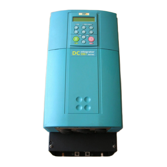
Eurotherm 590+ Series Product Manual (308 pages)
DC Digital Converter
Brand:
Eurotherm
| Category:
Media Converter
| Size: 4 MB
Table of Contents
Table of Contents
5
About this Manual
14
Chapter 1 Getting Started
14
Initial Steps
14
Packaging and Lifting Details
14
How the Manual Is Organised
15
An Overview of the Converter
17
How It Works
17
Control Features
18
Model Number (Europe)
19
Understanding the Product Code
19
Catalog Number (North America)
20
Door Assembly Product Code
21
Product Identification
21
Component Identification
22
Controller (Frames 1 & 2)
22
Door Assembly (Frames 3, 4, 5 & H)
23
Controller (Frame 3)
24
Controller (Frames 4 & 5)
25
Product (Frame H)
26
Installing the
27
Converter
27
Mechanical Installation
27
Unpacking the Converter
27
Lifting the Converter
27
Changing DC Output Terminals (Frame H)
28
Removing the Cover (Frame H)
28
Product Dimensions
29
AC Line Choke
30
Mounting the Converter
30
Recommended Tools
30
Ventilation and Cooling Requirements
30
Installing the External Vent Kit (Frames 4 & 5)
31
Installing the Fan (Frame H)
31
Electrical Installation
32
Minimum Connection Requirements (Frames 1, 2, 3, 4 & 5)
34
Important Connections
34
Protective Earth Connections (PE) - (Frames 1, 2, 3, 4 & 5)
35
Power Wiring Connections (Frames 1, 2, 3, 4 & 5)
36
Control Wiring Connections (Frames 1, 2, 3, 4 & 5)
39
Minimum Connection Requirements (Frame H)
43
Protective Earth Connections (PE) - (Frame H)
44
Power Wiring Connections (Frame H)
45
Control Wiring Connections (Frame H)
47
Motor Field Connections
48
Internal/External Supply (Frames 2, 3, 4 & 5)
48
Power Board - PCB Reference 385851 (Frame 3)
49
Power Board - PCB Reference 466701 (Frames 4 & 5)
50
External Connections (Frame H)
52
Optional Equipment
53
Fitting the Remote 6901 Operator Station
53
Speed Feedback and Technology Options
54
External AC Supply EMC Filter Installation
55
Earth Fault Monitoring Systems
56
Converter Installation Drawings
57
Installation Drawings
57
Filter Installation Drawings
68
Line Choke Installation Drawings
74
Operating the Converter
77
Pre-Operation Checks
77
Control Philosophy
78
Start/Stop and Speed Control
78
Selecting Local or Remote Control
79
Reading the Status Leds
79
Preliminaries
80
Analog Tacho Calibration Option Board
80
Microtach/Encoder Feedback Option Board
81
Setting-Up the Converter
80
Calibration
81
Selecting Speed Feedback
83
Initial Start-Up Routine
84
Performance Adjustment
90
Current Loop - the Autotune Feature
90
Speed Loop
90
Starting and Stopping Methods
91
Stopping Methods
91
Normal Stop (C3)
92
Program Stop (B8)
94
Coast Stop (B9)
95
Standstill
95
The Trip Condition
95
Advanced Starting Methods
96
Starting Several Converters Simultaneously
96
Jog
96
Crawl
96
Normal Starting Method
96
Equipment Inspection and Storage
14
Chapter 5 THE OPERATOR STATION
97
Connecting the Operator Station
97
Controlling the Operator Station
97
Control Key Definitions
98
Keys for Programming the Converter
98
Keys for Operating the Converter Locally
98
Indications
99
Operator Station Leds
99
Operator Station Alarm Messages
99
The Menu System
100
The Local Menu
101
The L/R Key
101
The PROG Key
101
Navigating the Menu System
102
Changing a Parameter Value
102
The Menu System Map
103
Menu Shortcuts and Special Key Combinations
104
Quick Tag Information
104
Changing the Stack Size (3-Button Reset)
104
Resetting to Factory Defaults (2-Button Reset)
105
Special Menu Features
106
Selecting a Menu Viewing Level
106
Selecting the Display Language
106
Password Protection
107
To Activate Password Protection
107
To Deactivate Password Protection
108
How to Save, Restore and Copy Your Settings
109
Saving Your Application
109
Restoring Saved Settings
109
Copying an Application
109
PROGRAMMING YOUR APPLICATION Programming with Block Diagrams
111
Modifying a Block Diagram
111
Configuration and Parameterisation Modes
111
Making and Breaking Links in Configuration Mode
111
Programming Rules
112
Saving Your Modifications
112
Understanding the Function Block Description
112
MMI Menu Maps
113
Function Block Descriptions
114
Analog Inputs
115
Analog Outputs
117
Aux I/O
118
BLOCK DIAGRAM (MMI Only)
123
Calibration
124
CONFIGURE DRIVE (MMI Only)
127
Current Loop
128
Current Profile
131
Diagnostics
132
Diameter Calc
137
Digital Inputs
139
Digital Outputs
141
Field Control
142
Alarms
145
Jog/Slack
148
Link 11 & Link 12
150
Menus
152
Minilink
153
Op Station
154
PASSWORD (MMI Only)
156
Chapter 3 PID
157
Chapter 4 RAISE/LOWER
160
Ramps
162
Setpoint Sum 1
166
Setpoint Sum 2
167
Speed Loop
169
Advanced
173
Standstill
174
Stop Rates
175
System Port P3
177
5703 Support
178
Taper Calc
179
Tec Option
180
Tens+Comp Calc
181
Torque Calc
183
User Filter
184
TRIPS and FAULT FINDING Trips
185
What Happens When a Trip Occurs
185
Converter Indications
185
Operator Station Indications
185
Resetting a Trip Condition
185
Fault Finding
186
Alarm Messages
186
Last Alarm
186
Health Word
186
Health Store
186
Hexadecimal Representation of Trips
187
Power Board LED Trip Information (Frame 4, 5 & H)
188
Using the MMI to Manage Trips
189
Trip Messages
189
Symbolic Alarm Messages
192
Self Test Alarms
192
Setting Trip Conditions
192
Viewing Trip Conditions
193
Inhibiting Alarms
193
Test Points
193
Chapter 8 ROUTINE MAINTENANCE and REPAIR
195
Maintenance
195
Service Procedures
195
Preventive Maintenance
195
Repair
195
Saving Your Application Data
195
Returning the Unit to Eurotherm Drives
196
Disposal
196
Technical Support Checks
197
Fuse Replacement (Frame H)
198
Product (Regenerative)
198
Product (Non-Regenerative)
199
Phase Assembly Replacement (Frame H)
200
Replacing the Fan (Frames 4 & 5)
202
CONTROL LOOPS Principle of Operation
203
Current Loop
203
Manual Tuning
204
Speed Loop
206
Field Control
206
Set-Up Notes
206
Current Control
207
Voltage Control
207
Field Weakening
207
Standby Field
207
A R a M E T E R P E C if IC a T Io N a B L E
209
Specification Table: Tag Number Order
210
Parameter Table: MMI Menu Order
226
Echnical Pecifications
237
Environmental Details
237
EMC Compliance
237
Electrical Ratings - Power Circuit
238
Power Supply Details
239
Auxiliary Power Supply Details
239
AC Line Choke (Frames 1, 2, 3, 4 & 5)
240
AC Line Choke (Frame H)
241
External AC Supply (RFI) Filters
241
Power Semiconductor Protection Fuses (Frames 1, 2, 3, 4 & 5)
242
Power Semiconductor Protection Fuses (Frame H)
242
Power Supply Fuses
243
Field Fuses
243
Earthing/Safety Details
243
Terminal Definitions (Digital/Analog Inputs & Outputs)
244
Terminal Information - Power Board (Frames 1, 2, 4 & 5)
245
Terminal Information - Control Board
248
Terminal Information (Frame H)
252
Terminal Information - Option Boards
253
Wiring Requirements for EMC Compliance
253
Wire Sizes and Termination Tightening Torques (Frames 1, 2, 3, 4 & 5)
254
Termination Tightening Torque (Frame H)
255
Cooling Fans
255
Spares List
256
Ertification for the
261
Requirements for EMC Compliance
261
Minimising Radiated Emissions
261
Earthing Requirements
261
Protective Earth (PE) Connections
261
Control/Signal EMC Earth Connections
262
Cabling Requirements
262
Planning Cable Runs
262
Increasing Motor Cable Length
262
EMC Installation Options
263
Screening & Earthing (Cubicle Mounted, Class A)
263
Star Point Earthing
264
Sensitive Equipment
265
Requirements for UL Compliance
266
Motor Overload Protection
266
Branch Circuit/Short Circuit Protection Requirements
266
Field Wiring Temperature Rating
267
Operating Ambient Temperature
267
Field Wiring Terminal Markings
267
Power and Control Field Wiring Terminals
267
Field Grounding Terminals
267
Field Terminal Kits
267
Fuse Replacement Information
267
Recommended Wire Sizes (Frames 1, 2, 4 & 5)
268
Recommended Wire Sizes (Frame H)
268
European Directives and the CE Mark
269
CE Marking for Low Voltage Directive
269
CE Marking for EMC - Who Is Responsible
269
Legal Requirements for CE Marking
270
Applying for CE Marking for EMC
270
Which Standards Apply
271
Basic and Generic Standards
271
Certificates
273
Quipment
275
Standard Equipment
275
Power Board Circuit Descriptions
275
AH470280U001, U002, U003, U004 (Frame 1)
275
AH470330 (Frame 2)
277
AH385851U002, U003, U004, U005 (Frame 3)
279
AH466701U001, U002, U003 (Frames 4 & 5)
284
AH466001U001, U101 (Frame H)
287
Optional Equipment
290
Speed Feedback Option Boards
290
Microtach Option Board
291
Wire-Ended Encoder Option Board
291
Tacho Calibration Option Board
291
Combined Tacho and Encoder Feedback
292
Communications Technology Options
292
COMMS Option Technology Box
292
E R Ia L O Mmu Nic a Tio Ns
293
Communications Technology Option
293
Config Ed Lite
293
System Port (P3)
294
UDP Menu Structure
294
UDP Transfer Procedure
294
MMI Dump
295
5703 Support
296
Commissioning the 5703/1
297
Error Codes
298
Error Report (Ee)
298
Chapter 15 THE DEFAULT APPLICATION
299
Chapter 13 Block Diagrams
299
Programming Block Diagram - Sheet 1
301
Programming Block Diagram - Sheet 2
302
Main Block Diagram
303
Field Control Block Diagram
304
Start/Healthy Logic Block Diagram
305
Functional Block Diagram
306
Advertisement
Advertisement
Related Products
Eurotherm 590L Series
Eurotherm 591H
Eurotherm 590H
Eurotherm 512C/04
Eurotherm 512C/08
Eurotherm 512C/16
Eurotherm 512C/32
Eurotherm 590SP
Eurotherm 590A SERIES
Eurotherm 583
Eurotherm Categories
Controller
Temperature Controller
Voice Recorder
Measuring Instruments
DC Drives
More Eurotherm Manuals
Login
Sign In
OR
Sign in with Facebook
Sign in with Google
Upload manual
Upload from disk
Upload from URL