Sign In
Upload
Manuals
Brands
Eubank Manuals
Air Conditioner
7AA1036A
Eubank 7AA1036A Air Conditioner Manuals
Manuals and User Guides for Eubank 7AA1036A Air Conditioner. We have
2
Eubank 7AA1036A Air Conditioner manuals available for free PDF download: Installation & Operation Manual
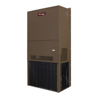
Eubank 7AA1036A Installation & Operation Manual (53 pages)
Vertical Wall-Mount Air Conditioners with Front Control Box Panel
Brand:
Eubank
| Category:
Air Conditioner
| Size: 4 MB
Table of Contents
Table of Contents
3
Chapter 1 Eubank Wall Mount Air Conditioner Description & Specifications
5
General Description
5
Serial Number Date Code
5
Air Flow, Weights and Filter Sizes
5
Model Identification
6
General Operation
7
Table 1 CFM @ External Static Pressure
7
Table 2 Return Air Filter Sizes
7
Table 3 Shipping Weights
7
Table 4 Ambient Temperature Operating Range
7
Optional Controls and Packages
8
Electrical Operation
10
Figure 1A. Typical Electrical Schematic - Non-Economizer
11
Figure 1B. Typical Electrical Schematic - W/Economizer
12
Figure 1C. Typical Electrical Schematic - W/Economizer (Alternate Construction)
13
Figure 1D. Typical Electrical Schematic - W/Economizer (Alternate Construction)
14
Figure 1E. Typical Electrical Schematic - W/Economizer (Alternate Construction)
15
Economizer Components
16
Figure 2. Dry Bulb Sensor
17
Figure 3. Enthalpy Sensor Temperature Control Points
18
Figure 4. Electrical Controls, Alternate Construction
18
Figure 5. Economizer Control Board
19
Chapter 2 Electronic Control Board
20
Introduction
20
Installation and Replacement
21
Operation
21
Figure 6A. Setting the Speed for the Y1 and Y2 Operation for Indoor Motor
22
Figure 6B. Second Stage Cooling Speed
22
Figure 7. Output Termination for Indoor Motor Control Signal
23
Figure 8. Outdoor Motor Speed Setting
23
Figure 9. Output Termination for Outdoor Motor Control Signal
23
Figure 10. Communications Setup
24
Sequence of Operation
25
Table 5. MODBUS Network Address DIP Swith Positions
25
Table 6A. MODBUS Discrete Registers
29
Table 6B. MODBUS Registers
30
Chapter 3 Installation
31
Equipment Inspection
31
Installation Requirements
31
Table 7 Minimum Clearances
32
Table 8 Voltage Limitations
32
Installation Materials
33
Porting and Duct Work
34
Fresh Air Hood Installation
35
Figure 11. Fresh Air Hood Damper, Models 1024A-1060A & 2036A-2060A
35
Table 9 Maximum Static Pressure
35
Bracket Installation
36
Mounting the Unit
36
Figure 12. Wall Mounting Detail
36
Electrical Connections
37
Figure 13A. Humidistat Wiring Details
39
Figure 13B. Thermostat Connection Diagram
39
Figure 13D. Commstat™ 3 HVAC Controller Wiring Detail
40
Chapter 4 Start-Up
41
Check-Out of Cooling Cycle
41
Check-Out of Heating Cycle
41
Chapter 5 Troubleshooting
42
Overview
42
Failure Symptoms Guide
42
Compressor Troubleshooting
43
Control Board Diagnosis
44
Chapter 6 Maintenance
45
Scheduled Maintenance
45
Chapter 7 Warranty
46
Airxcel Commercial Group Limited Product Warranty
46
Chapter 8 Start-Up Checklist
47
Start-Up & Commissioning Form
47
Appendix A
51
Installation Instructions for Field Installed Electric Heaters
51
Advertisement
Eubank 7AA1036A Installation & Operation Manual (55 pages)
Brand:
Eubank
| Category:
Air Conditioner
| Size: 3 MB
Table of Contents
Table of Contents
3
Air Flow, Weights and Filter Sizes
5
General Description
5
Serial Number Date Code
5
Table 1 Return Air Filter Sizes
5
Table 2 Refrigerant Charge
5
Table 3 CFM @ External Static Pressure
6
Table 4 Shipping Weights
6
Model Identification
7
General Operation
8
Optional Controls and Packages
8
Table 5 Ambient Temperature Operating Range
8
Electrical Operation
10
Figure 1A. Typical Electrical Schematic - Non-Economizer
11
Figure 1B. Typical Electrical Schematic - W/Economizer
12
Figure 1C. Typical Electrical Schematic - W/Economizer (Alternate Construction)
13
Figure 1D. Typical Electrical Schematic - W/Economizer (Alternate Construction)
14
Figure 1E. Typical Electrical Schematic - W/Economizer (Alternate Construction)
15
Chapter 2 Electronic Control Board
16
Introduction
16
Installation and Replacement
17
PCB Details and Information
17
Operation
21
Sequence of Operation
21
Figure 2. Enthalpy Sensor Temperature Control Points
26
Figure 3. Dry Bulb Sensor
27
Chapter 3 Installation
33
Equipment Inspection
33
Installation Requirements
33
Table 6 Minimum Clearances
34
Table 7 Voltage Limitations
34
Installation Materials
35
Porting and Duct Work
36
Fresh Air Hood Installation
37
Figure 4. Fresh Air Hood Damper, Models 1024A-1060A & 2036A-2060A
37
Table 8 Maximum Static Pressure
37
Bracket Installation
38
Mounting the Unit
38
Figure 5. Wall Mounting Detail
38
Electrical Connections
39
Figure 6A. Humidistat Wiring Details
41
Figure 6B. Thermostat Connection Diagram
41
Figure 6C. Commstat™ 3 HVAC Controller Wiring Detail
42
Chapter 4 Start-Up
43
Check-Out of Cooling Cycle
43
Check-Out of Heating Cycle
43
Chapter 5 Troubleshooting
44
Overview
44
Failure Symptoms Guide
44
Compressor Troubleshooting
45
Control Board Diagnosis
46
Chapter 6 Maintenance
47
Scheduled Maintenance
47
Chapter 7 Warranty
48
Eubank Limited Product Warranty
48
Chapter 8 Start-Up Checklist
49
Start-Up & Commissioning Form
49
Installation Instructions for Field Installed Electric Heaters
53
Advertisement
Related Products
Eubank 7AA1024A
Eubank 7AA1030A
Eubank 7AA1042A
Eubank 7AA1048A
Eubank 7AA1060A
Eubank 7AA2036A
Eubank 7AA2042A
Eubank 7AA2048A
Eubank 7AA2060A
Eubank 7AA1024H-1030H-1036H-1042H-1048H-1060H
Eubank Categories
Air Conditioner
Heat Pump
More Eubank Manuals
Login
Sign In
OR
Sign in with Facebook
Sign in with Google
Upload manual
Upload from disk
Upload from URL