Sign In
Upload
Manuals
Brands
ero electronic Manuals
Controller
PKP
ero electronic PKP Manuals
Manuals and User Guides for ero electronic PKP. We have
1
ero electronic PKP manual available for free PDF download: User Manual
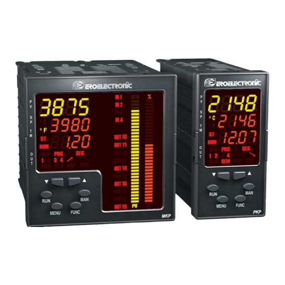
ero electronic PKP User Manual (173 pages)
Brand:
ero electronic
| Category:
Controller
| Size: 0 MB
Table of Contents
Table of Contents
3
Index
3
Mounting Requirements
5
Outline and Cut out Dimensions
6
Measuring Inputs
8
Connection Diagrams
8
Tc Input
9
Rtd Input
9
Thermocouple Input Wiring
9
Rtd Input Wiring
9
Inputs Wiring for 2-Wire Transmitter
10
MA, MV and V INPUTS WIRING
10
2, 3 and 4-Wire Transmitter Input
10
Linear Input
10
Inputs Wiring for 3-Wire Transmitter
11
Inputs Wiring for 4-Wire Transmitter
11
Auxiliary Input
12
Logic Inputs
12
Auxiliary Input Wiring
12
Logic Inputs Dig 1, 2, 3 Wiring
12
LOGIC INPUTS in 1, 2, 3 and 4 WIRING
13
LOGIC INPUTS in 5, 6, 7 and 8 WIRING
13
Current Transformer Input
14
Current Transformer Input Wiring
14
Relay Outputs
15
General Notes about Relay Output Wiring
16
Inductive Loads
16
Voltage Outputs for Ssr Drive
17
Ssr Drive Output Wiring
17
Triac Outputs
18
Switching Mode: Isolated Zero Crossing Type
18
Servomotor Output
19
Servomotor Output Wiring
19
Analog Outputs
20
Output 5 Wiring
20
Output 6 Wiring
20
Rs-485 Wiring
21
Serial Interface
21
Power Line Wiring
22
How to Remove the Instrument from Its Case
23
Preliminary Hardware Settings
23
Main Input Selection
24
Auxiliary Input Selection
24
Output 3 and 4 Selection
25
In Ct / Feedback Selection
25
Option Check
26
Operative Mode and Hardware Lock
27
General Notes
27
Security Code Setting Mode
27
Security Code Setting:
28
Run Time Security Code
28
Run Time Groups Protected by Security Code
29
Configuration Security Code
29
Run Time and Configuration Modes
30
General Note about Graphic Symbols Used for Mnemonic Code Visualization
30
Keyboard Description
31
Switch on the Instrument
32
Monitor Mode
33
Modify Mode
34
Configuration Group 1
35
Line Frequency
35
Main Input Type and Range
35
Decimal Point Position
37
Read-Out- Initial Scale Value
37
Square Root Extraction for Main Input
37
Filter on the Displayed Value
38
Offset on the Main Input
38
Read-Out- Full Scale Value
38
Auxiliary Input Function
39
Auxiliary Input Type
39
Full Scale Read-Out of the Auxiliary Input
39
Initial Scale Read-Out of the Auxiliary Input
39
Filter on Auxiliary Input
40
General Note about Configuration Group 1
40
OUT 1 Function
40
OUT 2 Function
41
OUT 3 Function
41
OUT 4 Function
41
Servomotor Type
41
OUT 5 Function
42
OUT 5 Range
42
OUT 5 Retransmission Initial Scale Value
42
Valve Position Indication
42
OUT 5 Filter on the Retransmitted Value
43
OUT 5 Retransmission Full Scale Value
43
OUT 6 Function
43
OUT 6 Range
43
General Note about Configuration Group 2
44
OUT 6 Filter on the Retransmitted Value
44
OUT 6 Retransmission Full Scale Value
44
Configuration Group 3
45
NOTE about the Split Range
45
Split Range
45
Main Control Output Bias
47
Main Control Output Gain
47
Secondary Control Output Bias
47
Secondary Control Output Gain
47
Main Control Output Conditioning
48
NOTE about Output Conditioning
48
Main Control Output in Engineering Unit
49
Main Output Decimal Point Position
49
Main Output Full Scale Readout
49
Main Output Initial Scale Readout
49
Main Output Auxiliary Conditioning
50
Secondary Control Output Conditioning
50
Secondary Control Output Decimal Point Position
51
Secondary Control Output Full Scale Value
51
Secondary Control Output in Engineering Unit
51
Secondary Control Output Initial Scale Value
51
General Note about Configuration Group 3
52
Secondary Output Auxiliary Conditioning
52
Auxiliary Control Configuration
53
Control Action Type
53
Manual Function
53
Smart Function
53
Controller
54
Device Status at Start up When It Works as
54
General Note about the Instrument Restarting
54
MANUAL to AUTO Transfer Type
54
Program Restarting after a Power Failure
55
Condition for Output Safety Value
56
Output Safety Value
56
Program Restart Tracking Band
56
Configuration Group 5
57
Logic Input "DIG 1" Function
57
Notes about Logic Inputs Used for Program Selection
58
Notes about Logic Inputs Used for RUN/HOLD Selection
58
Logic Input DIG 2 Function
59
Logic Input DIG1 - Contact Status
59
Logic Input DIG 2 - Contact Status
60
Logic Input DIG 3 Function
60
Logic Input DIG 3 - Contact Status
61
Logic Input in 1 Function
61
Event 1 Function
62
Logic Input in 1 - Contact Status
62
Event 1 Contact Status
63
General Notes about Configuration Group 5
64
Time for the "End of Cycle" Annunciator
64
Time for the "End of Profile" Annunciator
64
Bargraph Full Scale Value
65
Bargraph Initial Scale Value
65
Green Bargraph Function
65
Orange Bargraph Function
65
Operative Set Point Alignment at Start up
66
Resolution of the Deviation Bargraph
66
Set Point Display Type
66
Input Threshold to Enable the Soft Start
67
Servomotor Behaviour When the Output Power Is Limited
67
Time out Selection
67
Out Failure Detection (OFD)
68
Out Failure Detection - Output Assignment
68
Primary Current of the Current Transformer
68
Automatic Start Enabling
69
Current Time
69
Hysteresis of the Automatic Starting
69
Configuration Group Verf
70
Current Day
70
Auxiliary out 10 Status
71
Clock Calendar Test
71
Digital Input Dig.1 Status
71
OUT 1 Status
71
Configuration Group End
72
General Note for Configuration Group "Verf"
72
Configuration Mode
32
Run Time Mode
72
Preliminary
72
Control Parameters Protection
73
Control Parameters Modification
73
Run Time Group P [R.axx]
74
Program Editing
74
Run Time Group 2 [R.bxx]
75
Programmer/Controller Mode Selection
75
Main Set Point - [R.b02]
75
SMART Function - [R.b03]
75
Day of the Clock Start
76
Time of Clock Start
76
Current Time and Day
76
Group 2 Default Data Loading
77
Run Time Group 3
77
Manual Reset of the Alarms
77
Alarm 1 Threshold
77
Low Threshold Used When the Alarm 1 Is Band Alarm
78
Alarm 2 Threshold
78
High Threshold Used When the Alarm 1 Is Band Alarm
78
Low Threshold Used When the Alarm 2 Is Band Alarm
78
High Threshold Used When the Alarm 2 Is Band Alarm
79
Alarm 3 Threshold
79
Alarm 4 Threshold
79
Low Threshold Used When the Alarm 4 Is Band Alarm
80
High Threshold Used When the Alarm 4 Is Band Alarm
80
Output Failure Detection Low Alarm Threshold
80
Output Failure Detection High Alarm Threshold
80
Alarm 1 Hysteresis
81
Alarm 2 Hysteresis
81
Alarm 3 Hysteresis
81
Alarm 4 Hysteresis
81
Run Time Group 4
82
Proportional Band
82
Hysteresis (for ON/OFF Control)
82
Integral Time
82
Integral Preload
83
Relative Secondary Output Gain
83
Control Action
83
General Notes about PID Parameters
84
Proportional Band of the First PID Group
84
Hysteresis (for ON/OFF Control) of the First PID Group
85
Integral Time of the First PID Group
85
Derivative Time of the First PID Group
85
Integral Preload of the First PID Group
86
Relative Secondary Output Gain of the First PID Group
86
Group 4 Default Data Loading
86
Run Time Group 5
87
Anti Reset Wind up
87
Servo Motor Travel Time
87
Servo Motor Dead Band
87
Main Control Output Max Rate of Rise ]
88
Main Output Cycle Time
88
Secondary Control Output Low Limit
88
Secondary Control Output High Limit
88
Secondary Output Cycle Time
89
Set Point Low Limit -
89
Set Point High Limit
89
Rate of Change for Positive Set Point Variations
89
Time out for the Soft Start
90
External Control for AUTO /MANUAL Mode
90
External Control for Reverse/Direct Output Action Selection
90
Group 5 Default Data Loading
90
Run Time Group 6
91
Alarm 1 Type
91
Alarm 1 Configuration
91
Alarm 1 Action
93
Alarm 1 Stand by (Mask) Function -
93
Alarm 2 Type
94
Alarm 2 Configuration
94
Alarm 2 Action
95
Alarm 2 Stand by (Mask) Function
95
Alarm 3 Type
95
Alarm 3 Configuration
96
Alarm 3 Action
96
Alarm 3 Standby (Mask) Function
96
Alarm 4 Type
97
Alarm 4 Configuration
97
Alarm 4 Action
97
Alarm 4 Stand-By (Mask) Function
97
OFD (Output Failure Detection) Alarm Configuration
98
OFD (Output Failure Detection) Alarm Action
98
Group 6 Default Data Loading
98
Run Time Group 7 [R.gxx]
99
Serial Interface Protocol
99
Serial Link Device Address
99
Serial Link Baud Rate
99
Run Time Group 8
100
Feedback Potentiometer Adjustment Enabling
100
Servomotor Low Limit Positioning
100
Feedback Low Limit Calibration
100
Servomotor High Limit Positioning
101
Feedback High Limit Calibration
101
Group 8 Default Data Loading
101
Run Time Group 9
102
Tracking Group 1 - Tracking above
102
Tracking Group 1 - Tracking below
102
Group 9 Default Data Loading
103
Default Run Time Parameter Loading
103
Run Time Group "Hd"
104
Minimum Value of Proportional Band Calculated by SMART Algorithm
104
Maximum Value of Proportional Band Calculated by SMART Algorithm
104
Minimum Value of Integral Time Calculated by SMART Algorithm
104
Stand-By.
105
Hidden Group Default Data Loading
105
Programmer Mode
105
Edit
106
Manual
106
Run
106
Wait
106
Fast
107
Hold
107
Jump
107
Bargraph Description
108
Indicators
109
Display Function During Programmer Mode
110
When Device Operates in Programmer Mode and a Program Is Running
110
Output Power off Function
113
When Device Operates in Programmer Mode
113
Clock Calendar
114
Out Failure Detection Function (Ofd)
115
Serial Link
115
Lamp Test
116
Manual Mode
116
Direct Access to the Set Point
117
Edit Mode
118
General Notes about Program Editing
118
Program Selection
119
Ramp Time Engineering Units Selection
119
Run Time Group P
119
Soak Time Engineering Units Selection
119
Event 1 Enabling
120
Program 1 - Initial Set Point
120
Program 1 - Segment 1 - Final Set Point
120
Program 1 - Segment 1 - Gradient
121
Program 1 - Segment 1 - PID Group Selection
121
Program 1 - Segment 1 - Segment Duration
121
Program 1 - Segment 1 - Tracking Group Selection
121
Number of Program 1 Repetition
122
Program 1 - Segment 1 - Break Event 1 Status
122
Break Event Reset at the End of Program 1
123
Control Output at the End of Program 1
123
Control Type at the End of Program 1
123
PID Group at the End of Program 1
124
Program 1 - Timer Event 1 - Step 1
124
Set Point at the End of Program 1
124
General Notes about Timer Events
125
Number of Linked Program Repetitions
125
Selection of the Program to Add to the Selected Linked Program
125
How to Create a Simple Program
126
How to Modify a Segment
126
Simple Program Management
126
How to Add a Segment in an Existing Simple Program
127
How to Delete a Segment in an Existing Simple Program
128
How to Delete an Existing Simple Program
128
How to Create a Linked Program
129
Linked Program Management
129
How to Check a Program
130
How to Delete an Existing Linked Program
130
How to Modify a Linked Program
130
How to Run a Program (Simple or Linked)
131
Actions Available During Running Mode
132
Abort
133
Contoller Mode
135
Display Function During Controller Mode
136
Indicators Function During Controller Mode
138
Direct Access to the Set Point
138
Smart Function
139
Output Power off Function
140
Overrange, Underrange and Sensor Leads Break Detection
141
On the Main Input
141
Error Messages
141
On the Auxiliary Input
143
Other
143
Feedback Potentiometer Adjustment Error
144
Configuration and Run Time Parameter Errors
144
Calibration Parameter Errors
145
Other Errors
145
General Specifications
146
Power Consumption
146
General Informations
146
Installation Category
147
Rtd
148
Linear Inputs
148
Current Transformer Input for out Failure Detection
149
Control Actions
150
Output Limiters
151
Out 1 and 2 - SSR
152
Alarms
153
Events
154
Deviation Alarm
154
Alarm on the Main Output Value
154
Alarm on the Secondary Output Value
154
Auxiliary Power Supply
155
Maintenance
155
Default Run Time Parameters
156
Default Parameters
156
Default Configuration and User Parameters
161
Default Configuration and User Parameter Setting Group
162
Coding
170
Advertisement
Advertisement
Related Products
ero electronic PKC
ero electronic ELK Series
ero electronic ETK Series
ero electronic LDE
ero electronic LME
ero electronic MKC
ero electronic MKP
ero electronic RFS
ero electronic Categories
Controller
Temperature Controller
Measuring Instruments
Touch Panel
Control Systems
More ero electronic Manuals
Login
Sign In
OR
Sign in with Facebook
Sign in with Google
Upload manual
Upload from disk
Upload from URL