Sign In
Upload
Manuals
Brands
Ergon Manuals
Utility Vehicle
Crafco E-Z 1000 Series II
Ergon Crafco E-Z 1000 Series II Manuals
Manuals and User Guides for Ergon Crafco E-Z 1000 Series II. We have
1
Ergon Crafco E-Z 1000 Series II manual available for free PDF download: Parts Manual
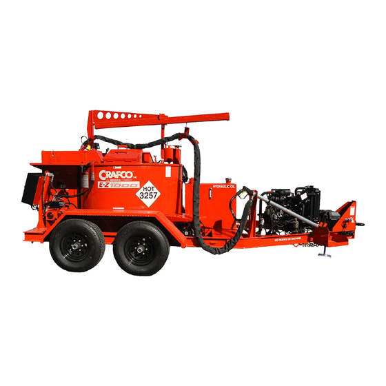
Ergon Crafco E-Z 1000 Series II Parts Manual (202 pages)
Melter
Brand:
Ergon
| Category:
Utility Vehicle
| Size: 13 MB
Table of Contents
Table of Contents
6
1 About this Manual
17
How to Use this Manual
17
2 Safety Precautions
19
General Safety
19
Personal Safety
19
Equipment or Operational Safety
19
California Proposition 65
20
All Crafco, Inc. Equipment
20
All Crafco, Inc. Equipment Using a Diesel Engine
20
Safety Symbols and Notices
21
Table 2-1 Safety Symbols and Notices
21
Table 2-2 Safety Symbols and Notices (Continued)
22
3 Limited Warranty
23
Warranty Claim Instructions
24
4 Machine Specifications
25
Table 4-1 Machine Specifications
25
5 Operating Instructions
27
Preparing the Machine for Start up
27
Table 5-1 Preparing the Machine for Start up
27
Fig. 5-1 Hydraulic Fluid Level and Temp. Gauge
28
Fig. 5-2 Dipstick
28
Fig. 5-3 Heat Transfer Oil Dipstick
28
Machine Start up for Electric Hose
29
Table 5-2 Starting the Burner for Electric Hose
29
Table 5-3 Starting the Burner for Electric Hose (Continued)
30
Machine Start up for Electric Compressor
31
Table 5-4 Starting the Burner for Electric Compressor
31
Table 5-5 Starting the Burner for Electric Compressor (Continued)
32
Altitude Compensation System (46200EB, 46200SB Only)
33
About the Heated Hose, Wand, Valve, and Tip Guard
33
Electric Hose Care and Cautions
34
Storing the Electric Hose for Transport
34
Table 5-6 Electric Hose Care
34
Table 5-7 Hose for Transport Instructions
34
Machine Start up for Standard Hose
35
Table 5-8 Starting Burner for Standard Hose
35
Machine Start up for Standard Compressor
36
Table 5-9 Starting Burner for Standard Hose (Continued)
36
Table 5-10 Starting the Burner for Standard Compressor
36
Table 5-11 Starting Burner for Standard Compressor (Continued)
37
Loading Material into the Sealant Tank
38
Table 5-12 Loading Material into the Sealant Tank
38
Material Tank Depth Chart
39
Table 5-13 Material Tank Depth Chart
39
Dispensing the Material
40
Table 5-14 Dispensing the Material - Electric Hose
40
Shutting down and Cleaning out the Machine
41
Table 5-15 Dispensing the Material - Standard Hose
41
Table 5-16 Shutting down 46200EB
42
Table 5-17 Shutting down 47600EC100
42
Table 5-18 Shutting down 46200SB
43
Table 5-19 Shutting down 47600SC100
43
Overnight Heater Use
44
Table 5-20 Overnight Heater Use
44
Storing the Machine
45
Air Compressor: PN 47600EC100, 47600SC100
46
Mounting a Skid Machine
47
Table 5-21 Mounting a Skid Machine
47
6 Maintenance Instructions
49
Engine
49
Air Compressor
49
Hydraulic System
49
Heat Transfer Oil
49
Wheel Bearing
49
Material Sensor Tube
49
Table 6-1 Air Compressor Maintenance Chart
49
Pump Packing Adjustment and Replacement
50
Lug Nuts
50
Brakes
50
Tongue Jack
50
Fig. 6-1 Lug Bolt Tightening Sequence
50
Temperature Control Calibration
51
Replacing Heat Transfer Oil
51
Cleaning Material Tank and Sensor Area
51
Cleaning the Melter
51
Fig. 6-2 Temperature Control Calibration
51
Maintenance Chart
52
Table 6-2 Maintenance Chart
52
Service Instructions
53
Table 6-3 Service Instructions
53
General Maintenance Parts
54
Table 6-4 General Maintenance Parts
54
Recommended Spare Parts
55
Recommended Fluids and Lubricants
55
Table 6-5 Recommended Spare Parts
55
Table 6-6 Recommended Fluids and Lubricants
55
Table 6-7 Applicable Brand of Heat Transfer Oil
55
Material Pump Replacement
57
Table 6-8 Material Pump Replacement
57
Fig. 6-3 Material Pump Replacement
58
Wand Repair Instructions
59
Cable Replacement
59
Switch Replacement
59
Terminal Block Replacement
59
Wand Handle Replacement
60
Fig. 6-4 Switch Wire Location
60
Fig. 6-5 Terminal Block Wiring
60
Fig. 6-6 Wire Routing
60
Fig. 6-7 Actuator Spring Location
61
Fig. 6-8 Actuator / Trigger Assembly
61
Burner Fuel Filter Replacement
62
Table 6-9 Burner Fuel Filter Replacement
62
7 How to Use a Multimeter
63
Checking DC Voltage with a Multimeter
63
Checking AC Voltage with Multimeter
63
Checking Resistance (Ohms)
63
Checking Amperage
64
Fig. 7-1 Standard Multimeter
64
Fig. 7-2 Clamp - on Amp Meter/Multimeter
65
8 Burner Troubleshooting
67
Table 8-1 Basic Visual Burner Troubleshooting
67
Table 8-2 Basic Visual Burner Troubleshooting (Continued)
68
Table 8-3 Burner Electrical Troubleshooting -4LE2 Engine
68
Table 8-4 Burner Electrical Troubleshooting - 4LE2 Engine (Continued)
69
Table 8-5 Burner Electrical Troubleshooting - 4LE2 Engine (Continued)
70
Table 8-6 Burner Electrical Troubleshooting - 4LE2 (Continued)
71
Table 8-7 Electrical Troubleshooting - 4LE2 Engine (Continued)
72
Fig. 8-1 ECM
73
Table 8-8 Burner Electrical Troubleshooting - 4LE2 Engine (Continued)
73
Fig. 8-2 Diesel Burner Schematic - 4LE2 Engine
74
Table 8-9 Burner Electrical Troubleshooting - 3C Engine
75
Table 8-10 Burner Electrical Troubleshooting - 3C Engine (Continued)
76
Table 8-11 Burner Electrical Troubleshooting - 3C Engine (Continued)
77
Table 8-12 Burner Electrical Troubleshooting - 3C Engine (Continued)
78
Fig. 8-3 Diesel Burner Schematic - 3C Engine
79
Table 8-13 Smoke Coming out of Exhaust Stack
80
Table 8-14 Burner Lights but Shuts down after 15 Seconds
80
Table 8-15 Testing the DC Controller
81
Table 8-16 Burner Fuel Solenoid Testing
81
Table 8-17 Burner Ignition Coil Test
82
Table 8-18 Bleeding the Burner - Non-Compressor Only
82
Fig. 8-4 Diesel Burner Electrode Adjustment
83
Fig. 8-5 Diesel Burner Air Settings
83
Sealant Heating Slowly
84
Table 8-19 Sealant Is Heating Slowly
84
Agitator Troubleshooting
85
Symptom: Mixer Does Not Rotate
85
Table 8-20 Basic Visual Mixer Troubleshooting
85
Table 8-21 Mixer Electrical Troubleshooting
86
Table 8-22 Mixer Electrical Troubleshooting (Continued)
87
Table 8-23 Mixer Electrical Troubleshooting (Continued)
88
Fig. 8-6 Checking Din Plug Voltage
89
Fig. 8-7 Mixer Circuit
90
Mixer Hydraulic Troubleshooting
91
Table 8-24 Mixer Hydraulic Troubleshooting
91
Fig. 8-8 Hydraulic Valve Pressure Setting
92
Fig. 8-9 Din Plug Layout
93
Hose Troubleshooting
94
Symptom: Hose Does Not Heat
94
Table 8-25 Basic Visual Troubleshooting
94
Table 8-26 Electrical Troubleshooting
94
Table 8-27 Electrical Troubleshooting (Continued)
95
Fig. 8-10 Junction Box Voltage Testing
96
Table 8-28 Electrical Troubleshooting (Continued)
96
Fig. 8-11 Hose Circuit Schematic
97
Fig. 8-12 Junction Box Wiring
98
Symptom: Trigger Is Not Working
99
Table 8-29 Trigger Is Not Working
99
RTD Sensor Ohms Vs. Temperature
100
Table 8-30 RTD Sensor Ohms Vs. Temperature
100
Table 8-31 RTD Sensor Ohms Vs. Temperature (Continued)
101
Pump Troubleshooting
102
Symptom: Material Does Not Dispense When the Pump Is Activated
102
Table 8-32 Basic Visual Pump Troubleshooting
102
Pump Hydraulic Troubleshooting
103
Table 8-33 Pump Electrical Troubleshooting
103
Table 8-34 Pump Electrical Troubleshooting (Continued)
104
Table 8-35 Pump Electrical Troubleshooting (Continued)
105
Fig. 8-13 Pump Circuit Schematic
106
Table 8-36 Pump Electrical Troubleshooting (Continued)
106
Table 8-37 Pump Hydraulic Troubleshooting
107
Engine Diagnostic Trouble Codes (DTC)
108
How to Use the Diagnostic Trouble Code Table
108
Engine DTC Table (47600EC100, 47600SC100)
108
Fig. 8-14 Engine Control Display DTC
108
Table 8-38 Engine DTC Table PN 47600EC100, 47600SC100
108
Table 8-39 Engine DTC Table PN 47600EC100, 47600SC100 (Continued)
109
Table 8-40 Engine DTC Table PN 47600EC100, 47600SC100 (Continued)
110
9 About the Illustrated Parts List
111
Ordering Crafco Parts
111
EZ1000 Series II EZ1000 Melters: 47600EC100 / 47600SB100 / 46200EB / 46200SB
112
Fig. 9-1 EZ1000 Series II Melters: 47600EC100 / 47600SB100 (NOT SHOWN)
112
Fig. 9-25 Material Pump Assembly
113
Fig. 9-2 EZ1000 Series II Melter: 47600EC100 / 47600SB100 (NOT SHOWN)
114
EZ1000 Series II Melter Options
118
Fig. 9-4 EZ1000 Series II Melter Options
118
Fig. 9-5 EZ1000 Series II Melter Options
120
Fig. 9-6 EZ1000 Series II Melter Options
122
Fig. 9-7 EZ1000 Series II Melter Options
124
Tank Detail
125
Fig. 9-8 Tank Detail
125
Plumbing
126
Fig. 9-9 Plumbing
126
Control Box Assembly 47202 - 46200EB
128
Fig. 9-10 Control Box Assembly 47202 - 46200EB
128
Fig. 9-11 Control Box Assembly 47202 - 46200EB
130
Control Box Assembly 47201 - 46200SB
132
Fig. 9-12 Control Box Assembly 47201 - 46200SB
132
Fig. 9-13 Control Box Assembly 47201 - 46200SB
134
Control Box Assembly 47210 - 47600EC100
136
Fig. 9-14 Control Box Assembly 47210 - 47600EC100
136
Fig. 9-15 Control Box Assembly 47210 - 47600EC100
138
Control Box Assembly 47215 - 47600SC100
140
Fig. 9-16 Control Box Assembly 47215 - 47600SC100
140
Fig. 9-17 Control Box Assembly 47215 - 47600SC100
142
Engine Assembly - Non Compressor
144
Fig. 9-18 Engine Assembly - 46200EB, 46200SB
144
Engine Assembly - 47600SC100
146
Fig. 9-19 Engine Assembly - 47600SC100
146
Engine Assembly 47600SC, 47600EC Air Filter Side
148
Fig. 9-20 Engine Assembly - 47600SC, 47600EC Air Filter Side
148
Engine Assembly - 47600EC100
150
Fig. 9-21 Engine Assembly - 47600EC100
150
Material Flow Control Assembly
152
Fig. 9-22 Material Flow Control Assembly
152
Hydraulic Compressor Valve Assembly
153
Fig. 9-23 Compressor Valve Assembly
153
Diesel Burner Assembly
154
Fig. 9-24 Diesel Burner
154
Material Pump Assembly
156
Air Compressor Assembly
158
Fig. 9-26 Compressor Assembly
158
High Output Air Lance Assembly
160
Fig. 9-27 High Output Air Lance Assembly
160
Wand Assembly
162
Fig. 9-28 Wand Assembly
162
Diesel Fuel Line Schematic - Non-Compressor
164
Fig. 9-29 Diesel Fuel Line Schematic - Non-Compressor
164
Diesel Fuel Line Schematic - Compressors
166
Fig. 9-30 Diesel Fuel Line Schematic - Compressors
166
Electrical Schematic - Electric Hose
168
Fig. 9-31 Electrical Schematic - 47600EC100
168
Electrical Schematic - Standard Hose
170
Fig. 9-32 Electrical Schematic - 47600SC100
170
Fig. 9-33 Optional Engine Cover for Compressor Models
172
Hot Air Lance
174
Fig. 9-34 Hot Air Lance (Option)
174
Jacketed Pump System
176
Fig. 9-35 Jacketed Pump System
176
Fig. 9-36 Jacketed Pump System
178
Hydraulic Control Valve Assembly
180
Fig. 9-37 Hydraulic Valve Assembly PN 45433
180
Hot Oil Pump and Motor
182
Fig. 9-38 Pump and Motor Assy, Hot Oil
182
Hydraulic System Diagram for Jacketed Pump Machines with the 23 HP Engine (46200EB, 46200SB)
184
Fig. 9-39 Hydraulic System Diagram - Non Compressor
184
Fig. 9-40 Hydraulic System Diagram - Non Compressor
186
Fig. 9-41 Hydraulic System Diagram - Non Compressor
188
Hydraulic System Diagram for Jacketed Pump Machines with the 42 HP Engine (47600EC100, 47600SC100, 47600ECPA, 47600SCPA)
190
Fig. 9-42 Hydraulic System Diagram - Compressor
190
Fig. 9-43 Hydraulic System Diagram - Compressor
192
Fig. 9-44 Hydraulic System Diagram - Compressor
194
10 Tools and Accessories
197
Advertisement
Advertisement
Related Products
Ergon Ergonomic Saddle Series
Ergon Crafco E-Z 49000N
Ergon CRAFCO E-Z 500 II Series
Ergon Crafco 46200EB
Ergon Crafco 46200SB
Ergon Crafco 47600EC100
Ergon Categories
Bicycle Accessories
Construction Equipment
Accessories
Farm Equipment
Mixer
More Ergon Manuals
Login
Sign In
OR
Sign in with Facebook
Sign in with Google
Upload manual
Upload from disk
Upload from URL