Sign In
Upload
Manuals
Brands
Enertech Manuals
Heat Pump
EME Series
Enertech EME Series Manuals
Manuals and User Guides for Enertech EME Series. We have
1
Enertech EME Series manual available for free PDF download: Installation & Operation Manual
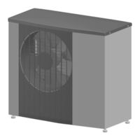
Enertech EME Series Installation & Operation Manual (104 pages)
AIR-TO-WATER HEAT PUMP
Brand:
Enertech
| Category:
Heat Pump
| Size: 10 MB
Table of Contents
Table of Contents
2
Section 1: Unit Nomenclature Model Nomenclature - EAV Series Unit
4
Model Nomenclature - EME/EMD Series Unit
4
Section 2: Installation Introduction
5
Inspection
5
Pre-Installation Steps
5
Section 3 - Installation Considerations Advantage Operating Envelope
6
Refrigerant Circuit - Cooling Mode
7
Refrigerant Circuit - Heating Mode
8
Refrigerant Circuit - Vapor Injection Heating Mode
9
Refrigerant Circuit - Active Defrost Mode
10
Refrigerant Circuit - Passive Defrost Mode
11
EAV Series Outdoor Unit Labels
12
EAV Series Outdoor Unit Controls
13
EAV Series Outdoor Unit Refrigerant Circuit
14
EME/EMD Indoor Module Cabinet Details
15
EAV Outdoor Unit Side Panel Removal
16
Unit Placement
18
Outdoor Unit Installation
18
Compressor Heater
18
Care
19
Installation Area
20
Assembly
21
Condensation
22
Overview
23
Components Needed for Enertech Recommendations
24
Designing the System
24
DHW Considerations
24
Indirect Tank Sizing
24
Backup Heat Considerations, EME (Electric Heat)
24
Backup Heat Considerations, EMD (Dual Fuel Backup)
24
Section 4: Dimensional and Physical Data Outdoor Unit Weight and Dimensional Data
25
Indoor Unit Weight and Dimensional Data
26
Hot Water Capacities‡ and Tank Dimensions
27
Section 5: Electrical Data
28
EAV Outdoor Unit Electrical Data
28
EME/EMD Indoor Module Electrical Data
28
Section 6: Unit Piping Installation Outdoor Application
29
Pipe Connections
30
Piping Connections
31
Preparation
32
Load Piping
33
Load Piping Installation
33
Piping Arrangement and Components
33
Other Hydronic Components
33
Piping Diagram - Piping between Outdoor Unit and Indoor Module
34
Piping Diagram - Indoor Module with Hydraulic Separator
35
Piping Diagram - Indoor Module with Buffer Tank
36
Piping Diagram - Indoor Module with Backup Boiler
37
Anti-Scald Valve Piping Connections
38
System Accessories Selection Table
39
Pump Mounting
39
Flow Rates and Piping Sizing
40
Piping Diagram - Flow Rates and Piping Sizing
41
Piping Diagram - Flushing Outdoor Unit Heat Exchanger and Piping
42
Piping Diagrams - Flushing Hot Water Tank
43
Piping Diagram - Flushing Piping between Indoor Module & Hydraulic Separator
44
Piping Diagram - Flushing Piping in Indoor Module
45
Piping Diagram - Flushing Piping on the Other Side of Hydraulic Separator, Step 1
46
Piping Diagram - Flushing Piping on the Other Side of Hydraulic Separator, Step 2
47
Piping Diagram - Flushing Zone 1 Radiant Floor Piping
48
Piping Diagram - Flushing Zone 2 Radiant Floor Piping
49
Piping Diagram - Flushing Air Handler (Fan Coil)
50
Piping Diagram - Flushing Hydronic Piping System
51
Piping Diagram - Flushing Boiler Piping
52
Piping Diagram - Final Position of Valves
53
Section 7: Water Quality & Antifreeze Load Side Antifreeze
54
Water Quality
54
Water Quality Table
55
Antifreeze Characteristics
56
Specific Gravity Table
57
Antifreeze Charging
58
Section 8: Field Wiring Electrical Connections
60
Communication
61
EAV Outdoor Unit and EME/EMD Indoor Module Communication Wires
62
Line and Low Voltage
63
Surge Protection
63
Hydro-Connect Zone Panels
65
EAV Input Requirements from Zone Panel
65
Zone Controls
66
Thermostats
67
Diagram HTG-1: Taco ZVC406 - Radiant Heating Only
68
Diagram HTGCLG-1: Heating/Cooling - One Fan Coil (Cooling or Heating & Cooling) up to 5 Radiant Heating Zones
69
Zones
69
Diagram HTGCLG-3: Heating/Cooling - A-Coil with Fossil Furnace Backup (A-Coil Cooling or Heating & Cooling) up to 5 Radiant Heating Zones
71
Diagram HTGCLG-5: Heating/Cooling - Multiple Fan Coils - no Radiant (All Fan Coils Are Enertech MPH Series)
72
Diagram HTGCLG-6:Heating/Cooling - Multiple Fan Coils - no Radiant (at Least One Fan Coil Has Y/W Inputs)
73
Heating/Cooling - Controls to be Used When a Buffer Tank Is Installed (at Least One Fan Coil Is Smaller than 2 Tons)
74
Section 9: On-Board Controls Outdoor Air Temperature (OAT)
75
Outdoor Control Box
76
Indoor Module Controls
77
Sensors
78
Human Machine Interface (HMI)
78
Pump Start
87
Troubleshooting
88
Section 10: Wiring Diagrams EAV Outdoor Unit Wiring Diagram
89
EME Indoor Module Wiring Diagram
90
EMD Indoor Module Wiring Diagram (Dual Fuel)
91
Section 11: Equipment Startup Form
92
Equipment Start-Up Form
92
Section 12: Troubleshooting Thermistor and Pressure Transducer Connections
93
Thermistor Legend
94
Type 1, Type 2, Type 3 Thermistor Tables
94
Outdoor Unit LED Status
95
Indoor, Outdoor, and Inverter Alarms Tables
97
Warranty Order & Claim Form
99
Warranty Registration Form
100
Revision Table
101
Advertisement
Advertisement
Related Products
Enertech EMD Series
Enertech EAV Series
Enertech EAV060
Enertech ERE48
Enertech ERE96
Enertech ERE120
Enertech ERE144
Enertech ERE168
Enertech ECV Series
Enertech ECH072
Enertech Categories
Burner
Heat Pump
Heater
Furnace
Air Conditioner
More Enertech Manuals
Login
Sign In
OR
Sign in with Facebook
Sign in with Google
Upload manual
Upload from disk
Upload from URL