Sign In
Upload
Manuals
Brands
EnerSys Manuals
Marine Radio
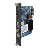
Alpha AlphaNet DOCSIS DM3EX
EnerSys Alpha AlphaNet DOCSIS DM3EX Manuals
Manuals and User Guides for EnerSys Alpha AlphaNet DOCSIS DM3EX. We have
1
EnerSys Alpha AlphaNet DOCSIS DM3EX manual available for free PDF download: Technical Manual
EnerSys Alpha AlphaNet DOCSIS DM3EX Technical Manual (100 pages)
Status Monitor for XM2
Brand:
EnerSys
| Category:
Marine Radio
| Size: 5 MB
Table of Contents
Table of Contents
4
1 Introduction
8
Fig. 1-1, Alphanet DM3X
8
Table 1-1, DM3X Transponder Model Specifications
8
Fig. 1-2, DM3X Transponder Components
9
2 Overview
10
System Diagram
10
Fig. 2-1, Representative System Arrangement
10
Network Connectivity
11
System Configuration and Installation
11
DM3.0 Series Start up and Reboot Routline
12
Fig. 2-2, DM3X Transponder Start up and Reboot Routline
12
Table 2-1, Leds and Indications
12
3 Network Configuration
13
Provisioning the DHCP Server with the MAC Addresses
13
Fig. 3-1, Locations of MAC Address Labels
13
Establishing IP Connectivity
14
The DOCSIS Configuration File
14
Setting Modem Community Strings - Docsdevnmaccess Method (Ipv4 Only)
15
Table 3-1, Modem Community String Parameters - Docsdevnmaccess Method
15
Setting Modem Community Strings - Coexistence Method
16
Table 3-2, Modem Community String Parameters - Coexistence Method
16
Setting SNMP Trap Destination Addresses - Docsdevnmaccess Method
17
Table 3-3, Trap Destination Addresses - Docsdevnmaccess Method
17
Setting SNMP Trap Destination Addresses - Coexistence Method
18
Table 3-4, Trap Destination Addresses - Coexistence Method
18
Sample DOCSIS Configuration File Entries - Devdocnmaccess
19
Sample DOCSIS Configuration File Entries - Coexistence
20
Proprietary Configuration File 'Atidoc33.Cfg
21
Changing Default Atidoc33.Cfg Download Settings
22
Table 3-5, Default Atidoc33.Cfg Download Settings
22
Setting Communication Options
23
Table 3-6, Communications Parameters
23
4 Web Interface
24
Local Web Server Access
24
Fig. 4-1, DM3X Web Page
24
Fig. 4-2, Local Area Connection Properties Screen, Windows 7
25
Remote Web Server Access
27
Fig. 4-6, Web Server Home Page
27
Navigating the Web Page
28
Fig. 4-7, Navigation Bar Items
28
Web Interface Security Levels
29
Table 4-1, DM3X Web Page Security
29
Table 4-2, DM3X Security Levels
29
Verifying Communication Parameters
30
Fig. 4-8, Communication Parameters
30
Fig. 4-9, Advanced Communication Parameters
30
Verifying Power Supply and Battery Parameters
31
Remote Self-Tests Via the Web Page
31
Fig. 4-10, Power Supply and Battery Parameters
31
Viewing HMS Alarm Status Via the Web Page
32
Fig. 4-11, HMS Alarm Configuration
32
Setting the I/O Controller Via the Web Page
33
Fig. 4-12, Advanced I/O Controller Status Screen
33
Viewing and Configuring Power Supply Settings Via the Web Page
34
Fig. 4-13, Advanced Power Supply Settings Screen
34
Viewing and Configuring Generator Settings Via the Web Page
37
Fig. 4-14, Advanced Generator Status Screen
37
Tools Menu - Constellation and Microreflections
38
QAM Constellation Tool
38
Fig. 4-15, QAM Constellation Tool
38
QAM Constellation Common Impairments
39
Fig. 4-16, Normal - (Good Quality) and Individual Cell Characteristics
39
Fig. 4-17, Fuzzy (Low CNR And/Or Low MER) and Individual Cell Characteristics
40
Fig. 4-18, Doughnuts (Coherent Interference) and Individual Cell Characteristics
40
Fig. 4-19, Gaussian Noise and Individual Cell Characteristics
41
Fig. 4-20, Rectangular Vs. Square (I-Q Imbalance) and Entire Constellation Shape
41
Fig. 4-21, Corners Squeezed to Center (Gain Compression) and Entire Constellation Shape
42
Fig. 4-22, Circular Smear (Phase Noise) and Entire Constellation Shape
42
Fig. 4-23, Twisted or Skewed (Quadrature Distortion) and Entire Constellation Shape
43
Microreflections Tool
44
Fig. 4-24, Microreflections Tool
44
Fig. 4-25, Spectrum Tool
45
Table 4-3, Spectrum Tool Buttons
45
Fig. 4-26, Spectrum Tables
46
Table 4-4, Spectrum Table Details
46
Viewing the Modem Event Log Via the Web Page
47
Fig. 4-27, Docsdev Event Log Screen
47
5 Upgrading Firmware
48
Upgrading DM3X Modem Firmware
48
Identifying the Modem and Obtaining Firmware Files
48
Modem Firmware Upgrade SNMP Parameters
48
Table 5-1, Modem Firmware Upgrade SNMP Parameters
48
Upgrading Manually by Setting SNMP Parameters
49
Upgrading Via the DOCSIS Configuration File
49
Table 5-2, SNMP Parameters
49
Table 5-3, DOCSIS Configurations File Values
49
6 Data Management
50
SCTE-HMS Mibs
50
Table 6-1, SCTE-HMS MIB Files
50
SCTE-HMS MIB Alarms
51
SCTE-HMS Configurable Alarms
51
Table 6-2, Binary to Hex Conversions for Alarm Settings
52
Table 6-3, Recommended Settings for DM3X Analog Alarms
53
Table 6-4, Recommended Settings for Discrete Alarms
54
Table 6-5, DM3X Alarm Setting Parameters
57
Table 6-6, Status of Alarm Setting Download Parameters
57
SNMP Traps
58
Table 6-7, SNMP Alarm Trap Varbinds and Explanations
59
General Power Supply Alarms
60
Table 6-8, Power Alarms: Classifications, Causes and Corrections
61
Table 6-8, Power Alarms: Classifications, Causes and Corrections, Continued
62
Table 6-8, Power Alarms: Classifications, Causes and Corrections, Continued
63
Battery Alarms
64
Table 6-9, Battery Alarms: Classifications, Causes and Corrections
64
7 Installation
65
Verifying Power Supply Device Address
65
Installation / Replacement Procedure in XM2 Power Supplies
66
Fig. 7-1, Captive Screw Locations
66
Fig. 7-2, Jumper Location and the 18-Pin Connector
67
Fig. 7-3, Connecting the Transponder to the Inverter Module
67
DM3X Leds and Connections
68
Fig. 7-4, DM3X Leds and Connectors
68
Connecting the RF Drop
69
Fig. 7-5, Connecting the RF Drop
69
Front Panel Connections
70
Fig. 7-6, System Interconnection Diagram
70
I/O Connections (TPR, ENV)
71
Tamper (TPR) Switch Interface
71
Fig. 7-7, I/O (ENV) and Tamper Switch Interface (TPR) Connection Locations
71
Table 7-1, Tamper (TPR) Switch Specifications
71
Configuring I/O Port Connections
72
I/O Port Interface
72
Table 7-2, ENV Connector and Pin Descriptions
72
I/O Port: Generic Device
73
Table 7-3, I/O Port Specifications
73
Table 7-4, I/O Port: Generic Device Specficiations
73
Configuring and Monitoring a Generic I/O Device
74
Connecting a Generic I/O Device
74
I/O Port: Heater Mat Control
75
Table 7-5, I/O Port: Heater Mat Control Specifications
75
Connecting the Battery Heater Mat Controller
76
Configuring the Battery Heater Mat Controller
77
I/O Port: Emergency DC Generator (GEN)
77
Table 7-6, Heater Mat Oids and Functionality
77
Table 7-7, Heater Mat MIB Reports
77
Configuring and Monitoring the DC Emergency Generator
78
Table 7-8, Generator Monitoring Values
78
8 Battery Sense Wire Kits
79
Single and Dual Strings
79
Fig. 8-1, 36V System, Single String
79
Fig. 8-2, 36V System, Dual String
79
Fig. 8-3, 48V System, Single String
80
Fig. 8-4, 48V System, Dual String
80
9 Start up and Verification
81
Initial Start up and Local Verification
81
Fig. 9-1, XM2 Smart Display Screens
81
Fig. 9-2, Communications Section - General Page
82
Verifying Correct Hardware Interconnection
83
Fig. 9-3, Power Supply Section - General Page
83
System Status Indicators and Reset Button
84
Fig. 9-4, LED Functionality and Indications
84
Detailed LED Descriptions
85
Table 9-1, SCTE-HMS Property Table
86
Table 9-2, Rx/Tx Power LED Color Ranges
86
Fig. 9-5, Transponder Web Page, RF Power Level Indicators
87
Resetting the Transponder
88
Verifying Communications Via the Headend
88
Dual IP Mode
89
Overview
89
Fig. 9-6, Simplified Block Diagram Single IP Mode
89
Fig. 9-7, Simplified Block Diagram Dual IP Mode
89
Table 9-3, Single IP Mode Vs. Dual IP Mode
89
Web Comparison, Single IP Mode/Dual IP Mode
90
Fig. 9-8, Single IP DM3X Transponder Web Page
90
Fig. 9-9, Dual IP DM3X Transponder Web Page
90
Configuring Dual IP Mode
91
Table 9-4, Enabling Dual IP Mode
91
Table 9-5, CPE Communications Module IP Settings
91
Fig. 9-10, Dual IP Configuration Settings for Web Server Communications Page
92
Fig. 9-11, Dual IP Parameters for Web Server General Page
92
Table 9-6, Available Download Options
93
Dual IP SNMP Community Strings
94
Table 9-7, Community Strings
94
Security in Dual IP Mode
95
Table 9-8, Data Access Key Parameters
95
Table 9-9, Secure Access Table Parameters
96
10 Specifications
97
11 Glossary
99
Acronym Definitions
99
Advertisement
Advertisement
Related Products
EnerSys Alpha AlphaNet DOCSIS DM3X Series
EnerSys PowerSafe DDm 85-13
EnerSys PowerSafe DDm 85-15
EnerSys PowerSafe DDm 85-21
EnerSys PowerSafe DDm 85-25
EnerSys PowerSafe DDm 100-27
EnerSys PowerSafe DDm 125-25
EnerSys PowerSafe DDm 125-33
EnerSys alpha DPX 1500W
EnerSys PowerSafe DDmP125-33 LP
EnerSys Categories
Camera Accessories
Battery Pack
Battery Charger
Power Supply
Industrial Equipment
More EnerSys Manuals
Login
Sign In
OR
Sign in with Facebook
Sign in with Google
Upload manual
Upload from disk
Upload from URL