
Summary of Contents for EnerSys Alpha AlphaNet DOCSIS DM3X Series
- Page 1 AlphaNet DM3X Series DOCSIS Status Monitor for XM2 ® Technical Manual Effective: June 2019...
- Page 2 Safety Notes Alpha considers customer safety and satisfaction its most important priority. To reduce the risk of injury or death and to ensure continual safe operation of this product, certain information is presented differently in this manual. Alpha tries to adhere to ANSI Z535 and encourages special attention and care to information presented in the following manner: WARNING! GENERAL HAZARD GENERAL HAZARD WARNING provides safety information to PREVENT INJURY OR DEATH to the techni-...
- Page 3 AlphaNet DM3X Series DOCSIS Status Monitor for XM2 ® Technical Manual 704-939-B10-001 Rev. A5 Effective Date: June 2019 © 2019 by Alpha Technologies Services, Inc. Disclaimer Images contained in this manual are for illustrative purposes only. These images may not match your installation. Operator is cautioned to review the drawings and illustrations contained in this manual before proceeding.
-
Page 4: Table Of Contents
Table of Contents 1.0 Introduction..........8 2.0 Overview . - Page 5 Table of Contents 7.0 Installation ..........65 7.1 Verifying Power Supply Device Address .
- Page 6 Figures Fig. 1-1, AlphaNet DM3X..........8 Fig.
- Page 7 Tables Table 1-1, DM3X Transponder Model Specifications....... 8 Table 2-1, LEDs and Indications ........12 Table 3-1, Modem Community String Parameters - docsDevNmAccess Method .
-
Page 8: Introduction
1.0 Introduction The AlphaNet DM3X Embedded DOCSIS and EuroDOCSIS Transponders allow monitoring of Alpha power supplies through existing cable network infrastructure. Advanced networking services provide quick reporting and access to critical powering information. This manual focuses on the DM3X Transponder complementing the XM2 CableUPS. The DM3X Transponder utilizes Simple Network Management Protocol (SNMP) and Management Information Bases (MIBs) to provide network status monitoring and diagnostics. -
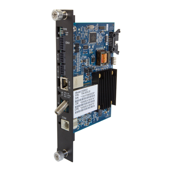
Page 9: Fig. 1-2, Dm3X Transponder Components
1.0 Introduction, continued Primary Features • DOCSIS 3.0 “Full Band Capture” Hardware • 10/100/1000 Mbps auto-negotiating standard Ethernet interface • Local Ethernet port provides technician on-site access to extensive power supply diagnostics* • Embedded Web server for direct diagnostics • Supports SNMPv1, v2c, v3 •... -
Page 10: Overview
2.0 Overview 2.1 System Diagram SNMP-based Network Management System DM3X Transponder Power Supply Coax/HFC Network CMTS TCP/IP Network External Generator DHCP Server TFTP Server TOD Server Web Browser Local Computer Fig. 2-1, Representative System Arrangement • All power supply data is stored in the power supply Inverter Module’s class information base (CIB) tables in the power supply. -
Page 11: Network Connectivity
2.0 Overview, continued 2.2 Network Connectivity The transponder’s cable modem must be provisioned to be recognized by the CMTS as a valid device to be assigned an IP address from the DHCP server, to locate the TFTP and TOD servers and to communicate with the SNMP management server (trap receiver). -
Page 12: Dm3.0 Series Start Up And Reboot Routline
2.0 Overview, continued 2.4 DM3.0 Series Start Up and Reboot Routline Network Management System TFTP Server MIB Browser TOD Server Web Browser DHCP Server Switches Routers Firewalls CMTS DM3X Transponder Power Supply Local Laptop Fig. 2-2, DM3X Transponder Start Up and Reboot Routline The above diagram, read left to right, indicates the order of operations as the transponder comes online. -
Page 13: Network Configuration
3.0 Network Configuration 3.1 Provisioning the DHCP Server with the MAC Addresses On the DHCP server, assign the cable modem’s CM MAC address with a DOCSIS Configuration File to set modem communication options. (See Section 3.3, The DOCSIS Configuration File for instructions on how to create a DOCSIS Configuration File). -
Page 14: Establishing Ip Connectivity
3.0 Network Configuration, continued 3.2 Establishing IP Connectivity The DM3X Transponder supports the CableLabs DOCSIS 3.0 IPv6 implementation. The main benefit of IPv6 is its expanded addressing capability, increasing the address space from 32 to 128 bits, providing virtually unlimited number of networks and systems. -
Page 15: Setting Modem Community Strings - Docsdevnmaccess Method (Ipv4 Only)
3.0 Network Configuration, continued 3.3.1 Setting Modem Community Strings - docsDevNmAccess Method (IPv4 Only) Set the modem community strings with the DOCSIS Configuration File by including the following SNMP parameters. Modem Community String Parameters docsDevNmAccess Method MIB Parameter Object ID Description Value docsDevNmAccessIp... -
Page 16: Setting Modem Community Strings - Coexistence Method
3.0 Network Configuration, continued 3.3.2 Setting Modem Community Strings - Coexistence Method Set the modem community strings with the DOCSIS Configuration File for an IPv6 network by including the following SNMP parameters: Modem Community String Parameters Coexistence Method TLV Parameter Description Value Type... -
Page 17: Setting Snmp Trap Destination Addresses - Docsdevnmaccess Method
3.0 Network Configuration, continued 3.3.3 Setting SNMP Trap Destination Addresses - docsDevNmAccess Method Set the SNMP Trap Destination Addresses via the DOCSIS Configuration File by including the following SNMP parameters. Trap Destination Addresses docsDevNmAccess Method MIB Parameter Object ID Description Value docsDevNmAccessIP 1.3.6.1.2.1.69.1.2.1.2.x IP address of trap... -
Page 18: Setting Snmp Trap Destination Addresses - Coexistence Method
3.0 Network Configuration, continued 3.3.4 Setting SNMP Trap Destination Addresses - Coexistence Method Set the SNMP Trap Destination Addresses via the DOCSIS Configuration File by including the following SNMP parameters: Trap Destination Addresses Coexistence Method TLV Parameter Description Value Type This config file element specifies an NMS that will receive notifications from the SNMPv3 Notification... -
Page 19: Sample Docsis Configuration File Entries - Devdocnmaccess
3.0 Network Configuration, continued 3.3.5 Sample DOCSIS Configuration File Entries - devDocNmAccess SNMP MIB Object (11) [Len=21]:docsDevNmAccessStatus.1/4 SNMP MIB Object (11) [Len=21]:docsDevNmAccesslp.1/10.56.21.0 SNMP MIB Object (11) [Len=21]:docsDevNmAccesslpMask.1/255.255.255.0 SNMP MIB Object (11) [Len=25]:docsDevNmAccessCommunity.1/”RW STRING” SNMP MIB Object (11) [Len=25]:docsDevNmAccessInterfaces.1/”@” SNMP MIB Object (11) [Len=21]:docsDevNmAccessControl.1/3 SNMP MIB Object (11) [Len=21]:docsDevNmAccessStatus.2/4 SNMP MIB Object (11) [Len=21]:docsDevNmAccesslp.2/10.20.30.40 SNMP MIB Object (11) [Len=21]:docsDevNmAccesslpMask.2/255.255.255.255... -
Page 20: Sample Docsis Configuration File Entries - Coexistence
3.0 Network Configuration, continued 3.3.6 Sample DOCSIS Configuration File Entries - Coexistence SNMPv1v2c Coexistence Configuration SNMPv1v2c Community Name:ReadWrite SNMPv1v2c Transport Address Access SNMPv1v2c Transport Address:0.0.0.0/0 SNMPv1v2c Transport Address Mask:0.0.0.0/0 SNMPv1v2c Transport Address Access SNMPv1v2c Transport Address:0:0:0:0:0:0:0:0/0 SNMPv1v2c Transport Address Mask:0:0:0:0:0:0:0:0/0 SNMPv1v2c Access View Type:read-write SNMPv1v2c Access View Name:docsisManagerView Docsis V3 Notification Receiver... -
Page 21: Proprietary Configuration File 'Atidoc33.Cfg
3.0 Network Configuration, continued 3.3.7 Proprietary Configuration File ‘atidoc33.cfg’ The DM3X Transponder will attempt to download a TLV-formatted file ‘atidoc33.cfg’ from the modem’s provisioning TFTP server at start up and every 24 hours thereafter. The atidoc33.cfg proprietary configuration file is optional and provides an alternative method to the modem’s DOCSIS configuration file for deploying Alpha proprietary SNMP MIB parameters to field-installed DM3.0 Series Communications Modules. -
Page 22: Changing Default Atidoc33.Cfg Download Settings
3.0 Network Configuration, continued 3.3.8 Changing Default atidoc33.cfg Download Settings By default, the DM3X Transponder will download the atidoc33.cfg file from the provisioning TFTP server every 24 hours. However, these settings may be adjusted per the tables below by placing the respective SNMP varbinds into the modem’s DOCSIS configuration file. -
Page 23: Setting Communication Options
3.0 Network Configuration, continued 3.4 Setting Communication Options Communications Settings may be changed through the Alpha MIB remotely using an SNMP MIB browser or automatically by placing the SNMP parameters into the DOCSIS Configuration File. NOTICE: Before setting options, verify UDP ports 37, 69, 161, 162 and TCP port 80 are not blocked. Communications Parameters SNMP Parameter Type... -
Page 24: Web Interface
4.0 Web Interface Overview The DM3X provides an embedded Web server interface to allow operations personnel the ability to connect locally or remotely via TCP/IP over Ethernet with a laptop/computer to verify the status of common data points and to configure various operating parameters. -
Page 25: Fig. 4-2, Local Area Connection Properties Screen, Windows 7
4.0 Web Interface, continued NOTICE: If you are unable to view the home page of the DM3X Transponder using IP address 192.168.100.1, the network configuration on the computer that is being used to connect to the DM3X Transponder may require a temporary static IP address (192.168.100.2) to be configured. - Page 26 4.0 Web Interface, continued Use the following procedure to configure a static IP address on a laptop or computer with the Windows 8 operating ® system: 1. Click the Start button (lower left button on most Windows computers). ® 2. When the window pops up, click Control Panel (usually about half the way down the second column).
-
Page 27: Remote Web Server Access
4.0 Web Interface, continued 4.2 Remote Web Server Access To remotely access the DM3X Web server utilizing a Web browser, use the following procedure: NOTICE: For Web server (HTTP) access, port 80 must not be blocked and the computer must have access to the private cable modem network 1. -
Page 28: Navigating The Web Page
4.0 Web Interface, continued 4.3 Navigating the Web Page Once the Web page has been successfully accessed, the operator is able to select a link on the header bar and the page specific to the topic will open enabling real-time data to be observed. See Fig. -
Page 29: Web Interface Security Levels
4.0 Web Interface, continued 4.3.1 Web Interface Security Levels The DM3X has two levels of function-specific security. General operations are Level 1. Configuration-related functions are Level 2. Refer to Table 4-1 for default User Name and Security Passwords. DM3.0 Series Transponder Web Page Security Function Value 1.3.6.1.4.1.4413.2.2.2.1.1.3.3.0... -
Page 30: Verifying Communication Parameters
4.0 Web Interface, continued 4.4 Verifying Communication Parameters Click the General menu of the web page to display common communication settings and values. Click the Advanced Communication menu to view additional communication parameters. Fig. 4-8, Communication Parameters Fig. 4-9, Advanced Communication Parameters 704-939-B10-001 Rev. -
Page 31: Verifying Power Supply And Battery Parameters
4.0 Web Interface, continued 4.5 Verifying Power Supply and Battery Parameters Click the General menu to access Power Supply and individual battery voltage values. Important parameters such as current alarm status, inverter status and tamper status can be quickly verified on this page. Additional power supply parameters can be viewed and configured on the Power Supply page located in the Advanced Configuration menu. -
Page 32: Viewing Hms Alarm Status Via The Web Page
4.0 Web Interface, continued 4.7 Viewing HMS Alarm Status via the Web Page HMS alarms levels and current states may be viewed by clicking on the HMS Alarms link on the Advanced Configuration menu (see Fig. 4-11). Parameter values cannot be edited on this Web page. An SNMP MIB browser or status monitoring software may be used for such edits. -
Page 33: Setting The I/O Controller Via The Web Page
4.0 Web Interface, continued 4.8 Setting the I/O Controller via the Web Page Access the I/O Environment page in the Advanced Configuration menu to adjust the settings for the Tamper Switch and I/O Controller. The Tamper Switch polarity may be changed by clicking on the preferred tamper switch polarity button. The I/O Controller section provides a user interface to select the type of device that will be connected and monitored via the ENV connector of the transponder. -
Page 34: Viewing And Configuring Power Supply Settings Via The Web Page
4.0 Web Interface, continued 4.9 Viewing and Configuring Power Supply Settings via the Web Page Click the Advanced Configuration menu and select Power Supplies to view connected power supply parameters. The power supply parameters with a formatted text box or a menu around the value can be configured. Click the Start Test button to remotely initiate power supply tests. - Page 35 4.0 Web Interface, continued Fig. 4-13, Advanced Power Supply Settings Screen, Continued NOTICE: When the Battery Model is set to “Other”, the battery charging parameters such as charger voltages, battery capacity, and temperature compensation can be customized, otherwise default values are populated for Alpha supported batteries.
- Page 36 4.0 Web Interface, continued Fig. 4-13, Advanced Power Supply Settings Screen, Continued 704-939-B10-001 Rev. A5 (06/2019)
-
Page 37: Viewing And Configuring Generator Settings Via The Web Page
4.0 Web Interface, continued 4.10 Viewing and Configuring Generator Settings Via the Web Page When a permanent, fixed generator is connected to a DM3X, the generator page listed in the Advanced Configuration menu will populate a list of the various parameters and alarm statuses. Generator Self-Tests may be remotely started by clicking on the Start Test button. -
Page 38: Tools Menu - Constellation And Microreflections
4.0 Web Interface, continued 4.11 Tools Menu - Constellation and Microreflections The Web Page of the DM3X provides some basic tools for analyzing impairments on the DOCSIS network. The “Tools” menu selection on the Web page provides access to the Constellation, Microreflections, and Spectrum tools. 4.11.1 QAM Constellation Tool The Constellation page provides a constellation view of the DOCSIS channel that may assist in identifying and troubleshooting common network impairments. -
Page 39: Qam Constellation Common Impairments
4.0 Web Interface, continued The tables on the right-hand side of the screen provide a summary of common parameters associated with QAM Constellation analysis. Here’s a breakdown of the parameters listed: • Frequency - The tuned downstream frequency given in MHz. •... -
Page 40: Fig. 4-17, Fuzzy (Low Cnr And/Or Low Mer) And Individual Cell Characteristics
4.0 Web Interface, continued Individual cells and entire QAM constellation Fig. 4-17, Fuzzy (Low CNR and/or Low MER) and Individual Cell Characteristics Individual cells and entire QAM constellation Fig. 4-18, Doughnuts (Coherent Interference) and Individual Cell Characteristics 704-939-B10-001 Rev. A5 (06/2019) -
Page 41: Fig. 4-19, Gaussian Noise And Individual Cell Characteristics
4.0 Web Interface, continued Individual cells and entire QAM constellation Fig. 4-19, Gaussian Noise and Individual Cell Characteristics Entire QAM constellation Fig. 4-20, Rectangular vs. Square (I-Q Imbalance) and Entire Constellation Shape 704-939-B10-001 Rev. A5 (06/2019) -
Page 42: Fig. 4-21, Corners Squeezed To Center (Gain Compression) And Entire Constellation Shape
4.0 Web Interface, continued Entire QAM constellation Fig. 4-21, Corners Squeezed to Center (Gain Compression) and Entire Constellation Shape Entire QAM constellation Fig. 4-22, Circular Smear (Phase Noise) and Entire Constellation Shape 704-939-B10-001 Rev. A5 (06/2019) -
Page 43: Fig. 4-23, Twisted Or Skewed (Quadrature Distortion) And Entire Constellation Shape
4.0 Web Interface, continued Entire QAM constellation Fig. 4-23, Twisted or Skewed (Quadrature Distortion) and Entire Constellation Shape 704-939-B10-001 Rev. A5 (06/2019) -
Page 44: Microreflections Tool
4.0 Web Interface, continued 4.11.3 Microreflections Tool The Microreflections page provides details about impairments on the DOCSIS network and the approximate distance(s) of the impairment(s). In order to provide the analysis and a display of possible impairments, this tool requires the Adaptive Equalization function to be enabled on the CMTS. -
Page 45: Fig. 4-25, Spectrum Tool
4.0 Web Interface, continued 4.11.4 Spectrum Tool Full-range display spanning 0 - 1005MHz, the Spectrum page provides a detailed, full-band capture analysis of the DOCSIS Channels for the DM3X. This tool assists in identifying and troubleshooting common impairments throughout the range of DOCSIS Channels. -
Page 46: Fig. 4-26, Spectrum Tables
4.0 Web Interface, continued The tables on the right of the Spectrum page detail the X-Axis (Frequency), the Y-Axis (Amplitude), and the settings for the Spectrum display. Fig. 4-26, Spectrum Tables Spectrum Tool Features Feature Function Frequency (X-Axis) Center Frequency (MHz) The frequency in the center of the display. -
Page 47: Viewing The Modem Event Log Via The Web Page
4.0 Web Interface, continued 4.12 Viewing the Modem Event Log via the Web Page View the transponder’s event log by clicking the History drop down menu and select Modem Log. This will display the Docsdev Event Log. The log may be reset by clicking on the Reset Log button or the logged data may be downloaded by clicking on the Download CSV button. -
Page 48: Upgrading Firmware
5.0 Upgrading Firmware 5.1 Upgrading DM3X Modem Firmware The firmware is upgraded using standard DOCSIS methods as defined in RFC4639. There are two ways to upgrade the modem’s firmware: By directly setting the appropriate MIB parameters in the docsDevSoftware branch, or by including the appropriate SNMP parameters and values in the modem’s DOCSIS Configuration File, stored in the TFTP root directory. -
Page 49: Upgrading Manually By Setting Snmp Parameters
5.0 Upgrading Firmware, continued 5.1.3 Upgrading Manually by Setting SNMP Parameters 1. Acquire the firmware and CVC files for your DM3X from Alpha Technologies Services, Inc. 2. Import the CVC into the modem’s DOCSIS Configuration File (to create a Configuration File, see Section 3.3, The DOCSIS Configuration File). -
Page 50: Data Management
6.0 Data Management 6.1 SCTE-HMS MIBs The DM3X remotely reports power supply data and alarms using the Simple Network Management Protocol (SNMP) over the DOCSIS (Data Over Cable Service Interface Specification) communications standard. The DM3X typically reports into a centralized Network Management System (NMS) through a standard collection of data access points referred to as the SCTE-HMS Management Information Bases (MIBs). -
Page 51: Scte-Hms Mib Alarms
6.0 Data Management, continued 6.2 SCTE-HMS MIB Alarms 6.2.1 SCTE-HMS Configurable Alarms The HMS discrete and analog alarms provide the capability to monitor and alarm various power supply and environmental conditions and measurements. The alarms in the SCTE-HMS propertyTable and the discretePropertyTable can be defined and set to provide a custom monitoring system. -
Page 52: Table 6-2, Binary To Hex Conversions For Alarm Settings
6.0 Data Management, continued Binary to Hex Conversions for Alarm Settings Unused HiHi LoLo Enabled Alarms Bit 7 Bit 6 Bit 5 Bit 4 Bit 3 Bit 2 Bit 1 Bit 0 No Alarms LoLo Lo, LoLo Hi, LoLo Hi, Lo Hi, Lo, LoLo HiHi HiHi, LoLo... -
Page 53: Table 6-3, Recommended Settings For Dm3X Analog Alarms
6.0 Data Management, continued The following table displays the various analog alarms with common settings for the DM3X. Analog Alarms and Common Settings Alarm Analog Alarms Description LOLO HIHI Deadband Enable Scaled representation of the full psTotalStringVoltage 0x0F 3300 3500 4520 4570 battery string in 1/100 Volts units... -
Page 54: Table 6-4, Recommended Settings For Discrete Alarms
6.0 Data Management, continued Recommended Settings for Discrete Alarms Discrete Alarms Description Setting psInverterStatus (1) Inverter Off Disable Inverter Running Due to Loss of AC psInverterStatus (2) discreteMinor Line Voltage psInverterStatus (3) Self-Test Initiated Locally Disable psInverterStatus (4) Self-Test Initiated Remotely Disable psInverterStatus (5) Last Self-Test Failed... - Page 55 6.0 Data Management, continued Discrete Alarms for Optional Generator Discrete Alarms Description Setting genGeneratorStatus (1) Generator OFF Disable genGeneratorStatus (2) Generator Running (Test) discreteMinor genGeneratorStatus (3) Generator Running discreteMajor genGeneratorStatus (4) Generator Fail discreteMajor genGasHazard (1) No Alarm Disable The concentration of hydrocarbon fuel in the generator enclosure has exceeded safe limits.
- Page 56 6.0 Data Management, continued Discrete Alarms for Optional Generator, continued Discrete Alarms Description Setting The generator is indicating a minor alarm. The generator requires genMinorAlarm (2) discreteMinor attention but does not require an immediate visit to the site. genMajorAlarm (1) No Alarm Disable The generator is indicating a major...
-
Page 57: Table 6-5, Dm3X Alarm Setting Parameters
6.0 Data Management, continued 2. Export the “AlarmSetting.acf” file of the master transponder’s alarm settings. 3. Connect to the Web page of the master transponder. 4. Navigate to the Advanced Configuration menu and select the HMS Alarms page. 5. Verify the alarm settings defined in Step 1 are displayed in the propertyTable and discrete PropertyTable. If further changes to the alarm settings are required, refer to Step 1. -
Page 58: Snmp Traps
6.0 Data Management, continued 6.2.2 SNMP Traps Use of SNMP Traps allow the network manager to set conditions (alarms) under which the device (or devices) autonomously reports to the headend the existence of the pre-configured event. The type of event determines the level of action to be taken. -
Page 59: Table 6-7, Snmp Alarm Trap Varbinds And Explanations
6.0 Data Management, continued When viewed through a third-party trap receiver, the translated varbinds and data values will be displayed in a format similar to the sample below: Bindings (5) Binding #1: commonPhysAddress.0 *** (octets) 00:90.EA.A0.01.4E (hex) Binding #2: commonLogicalID.0 *** (octets) (123 Example Ave.) Binding #3: alarmLogInformation.1 *** (octets) 00.00.00.76.07.10.06.0D.2B.06.01.04.01.AB.57.01.04.02.01. -
Page 60: General Power Supply Alarms
6.0 Data Management, continued Trap on Normal The DM3X has the capability of sending a “return to normal” trap once an alarmed condition returns to a normal state. This feature is enabled by default but can be disabled by setting the TRAP ON NORMAL parameter in the MIB point atiMgmtSnmpTrapOnNormal to a value of “2”. -
Page 61: Table 6-8, Power Alarms: Classifications, Causes And Corrections
6.0 Data Management, continued The following table lists the psMajor and psMinor alarm definitions for the XM2 power supply. Power Alarms: Classifications, Causes and Corrections Alarm Active Alarm Probable Causes of Alarm Corrective Action Type 1. Check/correct other alarms. 2. Check that correct AC Input Voltage is •... -
Page 62: Table 6-8, Power Alarms: Classifications, Causes And Corrections, Continued
6.0 Data Management, continued Power Alarms: Classifications, Causes and Corrections Alarm Active Alarm Probable Cause of Alarm Corrective Action Type 1. Check for AC Input Voltage present 2. Check Output current on the display. If Output Current is > 100% of rating, correct overload conditions. -
Page 63: Table 6-8, Power Alarms: Classifications, Causes And Corrections, Continued
6.0 Data Management, continued Power Alarms: Classifications, Causes and Corrections Alarm Active Alarm Probable Cause of Alarm Corrective Action Type 1. Check Inverter OVERTEMP Major Inverter heat sink over temperature. 2. Check PDB 3. Check Enclosure Ventilation A power supply has failed and the N+1 system has 1. -
Page 64: Battery Alarms
6.0 Data Management, continued 6.2.4 Battery Alarms The Intelligent CableUPS detects a wide array of battery alarms and displays the type of active alarm in the Smart Display screen and the severity of alarm (e.g., Major/Minor) by means of the Inverter Module LEDs. Battery Alarms: Classifications, Causes and Corrections Alarm Active Alarm... -
Page 65: Installation
7.0 Installation 7.1 Verifying Power Supply Device Address Before installing the hardware, provision the DHCP server with the cable modem’s CM MAC address. This allows the installation to be verified while the technician is on-site, eliminating the need for a second visit if there are problems with the installation. -
Page 66: Installation / Replacement Procedure In Xm2 Power Supplies
7.0 Installation, continued 7.2 Installation / Replacement Procedure in XM2 Power Supplies NOTICE: The DM3X is powered via the Battery A/B Sense/Power Harness. The sense harness must be connected to the batteries before being plugged into the DM3X A/B connector to power the transponder. If the XM2 CableUPS has been shipped without a DM3X Transponder, or the existing module requires removal and replacement, do so via the following procedure: 1. -
Page 67: Fig. 7-2, Jumper Location And The 18-Pin Connector
7.0 Installation, continued Place the jumper on positions 2 and 3 for an XM2 installation Fig. 7-2, Jumper Location and the 18-Pin Connector 1. Verify the Jumpers (J10 and J11) on the transponder are in the correct position for an XM2 installation (See Fig. 7-2). -
Page 68: Dm3X Leds And Connections
7.0 Installation, continued 7.3 DM3X LEDs and Connections DM3X LEDs and Connectors LED or Item Status Behavior Indication Connector TPR: Tamper Switch Connector RST: Reset Button ALM/ ON (steady) if Battery String(s) BAT A / B ON / OFF Connected Correctly BAT A / B Connector ON (steady) if Battery String(s) BAT C / D... -
Page 69: Connecting The Rf Drop
7.0 Installation, continued 7.4 Connecting the RF Drop CAUTION! Install a grounded surge suppressor (Alpha P/N 162-028-10 or equivalent). Failure to install an appropriate surge suppressor may void the warranty NOTICE: Alpha Technologies Services, Inc. recommends tightening the RF cable connector and the cables attached to the Grounded Surge Protector to a torque setting of 10in-lb ±... -
Page 70: Front Panel Connections
7.0 Installation, continued 7.5 Front Panel Connections NOTICE: Alpha Technologies Services, Inc. recommends tightening the RF cable connector and the cables attached to the Grounded Surge Protector to a torque setting of 10in-lb ± 1in-lb. Generator (ECM) (Alpha p/n 744-726-XX) Communications Port Alpha Bus Cable ECM Interface... -
Page 71: I/O Connections (Tpr, Env)
7.0 Installation, continued 7.6 I/O Connections (TPR, ENV) The Alpha DM3X Transponders are all populated with a Tamper interface to report the status of the power supply enclosure door when equipped with the optional tamper switch. The Alpha DM3X Transponders are populated with the Environmental and I/O Controller interface (referred to in this section as I/O Port) which can be used to monitor and control an array of contact relay devices such as battery heater mats, enclosure moisture sensors and emergency generators. -
Page 72: I/O Port Interface
7.0 Installation, continued 7.6.2 I/O Port Interface ENV Connector and Pin Descriptions ENV Connector Description Logic Gnd 5V +/- 0.5V voltage Shotky Protection – 15mA max. – Relay current drive Open/Close Control – 0V/15mA sink = Close, 3.3V/0mA = Open Open/Close Sense –... -
Page 73: I/O Port: Generic Device
7.0 Installation, continued I/O Port Specifications atiMgmtSysIoSelect (1.3.6.1.4.1.926.1.3.2.8.1.0) MIB Value Device Reported Parameter of MIB Branch No Device (Generic) I/O Pins Only LAP Only atiMgmtSysIoLAPState 1.3.6.1.4.1.926.1.3.2.8.2.0 Heater Control Only atiMgmtSysTempMgr * 1.3.6.1.4.1.926.1.3.2.4 DC Generator Only atiMgmtSysIoGenState 1.3.6.1.4.1.926.1.3.2.8.3.0 Heater Control and atiMgmtSysIoLAPState atiMgmtSysTempMgr * Generator and LAP atiMgmtSysIoLAPState atiMgmtSysIoGenState... -
Page 74: Connecting A Generic I/O Device
7.0 Installation, continued 7.6.5 Connecting a Generic I/O Device For generic device configurations consult your Alpha representative. 7.6.6 Configuring and Monitoring a Generic I/O Device Set the parameter atiMgmtSysIoSelect 1.3.6.1.4.1.926.1.3.2.8.1.0 to a value of “1” (Generic). Alternatively, navigate to ‘Advanced Configuration’, ‘I/O – Environment’ and select “Generic Device” from the pull-down list. The status of the control and input pins can be monitored through the following OIDs. -
Page 75: I/O Port: Heater Mat Control
7.0 Installation, continued 7.6.7 I/O Port: Heater Mat Control NOTICE: The Heater Control MIBs will continue to report regardless of atiMgmtSysIoSelect value, but the Web page will only display Heater Control status if atiMgmtSysIoSelect is set to “3” or “5.” atiMgmtSysIoSelect = 3,5 A battery heater mat controller may be managed though the following set of parameters within the ‘atiMgmtSysTempMgr’... -
Page 76: Connecting The Battery Heater Mat Controller
7.0 Installation, continued 7.6.8 Connecting the Battery Heater Mat Controller Power to the heater mat is provided via a customer-supplied controller plugged into the power outlet inside the enclosure. A cable (Alpha p/n 875-627-22) connects the controller to the ENV (Environmental) connector on the transponder. The connection procedure is shown below. -
Page 77: Configuring The Battery Heater Mat Controller
7.0 Installation, continued 7.6.9 Configuring the Battery Heater Mat Controller In this example, values are written to their respective OIDs to set temperatures, control mode and status reporting. Heater Mat OIDs and Functionality Set these OIDs to the Specified Value Functionality atiMgmtSysTempTemperature Heater turns on at 5°C... -
Page 78: Configuring And Monitoring The Dc Emergency Generator
7.0 Installation, continued 7.6.11 Configuring and Monitoring the DC Emergency Generator Set the parameter atiMgmtSysIoSelect 1.3.6.1.4.1.926.1.3.2.8.1.0 to a value of “4” (Generator). Alternatively, navigate to ‘Advanced Configuration’, ‘I/O – Environment’ and select “Generator Only” from the pull-down list. The status of the Generator can be monitored through I/O – Environment web page or via the SNMP MIB atiMgmtSysIoGenState 1.3.6.1.4.1.926.1.3.2.8.3.0. -
Page 79: Battery Sense Wire Kits
8.0 Battery Sense Wire Kits 8.1 36V Single and Dual Strings Battery Sense Wire Kits are required to power the transponder, as well as for individual battery voltage monitoring. The Battery Sense Wire Kits are connected to the transponder battery connections A/B for battery strings 1 and 2 and the C/D connector for battery strings 3 and 4. -
Page 80: Fig. 8-3, 48V System, Single String
8.0 Battery Sense Wire Kits, continued To Power Supply To Power Supply Black Black Neg - Neg - Neg - Neg - Sense Wire Kits: Neg - Neg - Neg - Neg - Alpha P/N: 874-841-21 (6') Alpha P/N: 874-841-25 (9') Pos + Pos + Pos +... -
Page 81: Start Up And Verification
9.0 Start Up and Verification 9.1 Initial Start Up and Local Verification To confirm successful hardware installation before leaving the installation site, verify network connectivity and correct hardware interconnection. To Verify Network Connectivity: The DS and REG LEDs on the front of the DM3X Transponder should be ON solid green. This indicates successful registration with the headend. -
Page 82: Fig. 9-2, Communications Section - General Page
9.0 Start Up and Verification, continued Connect a computer’s network port to the transponder’s Ethernet port using a standard network cable. Launch an Internet browser and enter 192.168.100.1 into the address. The transponder will return the Web page shown below. Click on General to display the key communications parameters including system uptime, IP provisioning mode (IPv4, IPv6 &... -
Page 83: Verifying Correct Hardware Interconnection
9.0 Start Up and Verification, continued 9.2 Verifying Correct Hardware Interconnection NOTICE: The DM3X model provides both BAT A/B and BAT C/D LED indicators and battery harness connectors (supports a maximum 4 battery strings). The BAT A/B and BAT C/D LED indicators on the front panel of the DM3X unit should illuminate solid green once the battery wiring harnesses are correctly installed. -
Page 84: System Status Indicators And Reset Button
9.0 Start Up and Verification, continued 9.3 System Status Indicators and Reset Button As viewed from the front of the unit, the DM3X Transponder utilizes LEDs to indicate system status. During system start up, the LEDs will first blink momentarily then indicate the current status of a variety of parameters on the DM3X Transponder. -
Page 85: Detailed Led Descriptions
9.0 Start Up and Verification, continued 9.3.1 Detailed LED Descriptions After power is applied or a reset occurs, all LEDs will flash in certain patterns indicating the cable modem chipset is starting or restarting. Once it is ready, it will begin the DOCSIS requirement of searching for the downstream frequency lock and the LEDs will follow the detailed descriptions below. -
Page 86: Table 9-1, Scte-Hms Property Table
9.0 Start Up and Verification, continued Rx/Tx Power The Rx/Tx PWR LED utilizes a tricolor LED to provide the installer a quick verification of the modem transmit (Tx) and receive (Rx) RF power levels. The Rx/Tx PWR LED will illuminate green when both the cable modem Tx and cable modem Rx RF power levels are within the range as specified in the SCTE-HMS PropertyTable. -
Page 87: Fig. 9-5, Transponder Web Page, Rf Power Level Indicators
9.0 Start Up and Verification, continued Rx/Tx Power The current RF level status for both the Rx and Tx will be displayed on the colored scale highlighted in black, providing verification of modem RF power levels. Refer to the figure below for an example of the RF power level indicator bars on the Web page. -
Page 88: Resetting The Transponder
9.0 Start Up and Verification, continued 9.3.2 Resetting the Transponder Should the need arise to reset the transponder locally, such as in the case of adding additional power supplies, a generator, or carrying out maintenance activities, do the following: Press and hold the reset button (RST) for approximately three (3) seconds until the ALM/RDY LED stops blinking and turns solid (green). -
Page 89: Dual Ip Mode
9.0 Start Up and Verification, continued 9.5 Dual IP Mode 9.5.1 Overview The DM3X Transponder can operate in either Single (default) or Dual IP mode. In Single IP mode, data from both the cable modem and power supply are accessed and managed through the modem’s IP address on the secure private modem network. -
Page 90: Web Comparison, Single Ip Mode/Dual Ip Mode
9.0 Start Up and Verification, continued 9.5.2 Web Comparison, Single IP Mode/Dual IP Mode To easily determine the configuration of the Communications Module when viewing it on its web page, check the Configuration line as well as the entries for the CM and CPE addresses. A single IP Communications Module will display a CM MAC address only, while a Dual IP Communications Module will also indicate a CPE address. -
Page 91: Configuring Dual Ip Mode
9.0 Start Up and Verification, continued 9.5.3 Configuring Dual IP Mode To switch the DM3X Transponder from Single to Dual IP mode the atiMgmtSnmpSnmpCPEAccess parameter of the Alpha MIB will need to be enabled. The Dual IP enable setting can be set through the DOCSIS Configuration File, the DM3.0 Setup File (atidoc33.cfg), the Provisioning Mode via the Communications Web page or remotely using SNMP by setting the following Alpha MIB: Enabling Dual IP Mode... -
Page 92: Fig. 9-10, Dual Ip Configuration Settings For Web Server Communications Page
9.0 Start Up and Verification, continued To change the CPE IP address allocation option from DHCP to Static via the Web Server, refer to the following: 1. Connect to DM3X Transponder via Web browser per the procedure in Section 4.0, Web Interface. 2. -
Page 93: Table 9-6, Available Download Options
9.0 Start Up and Verification, continued atidoc33.cfg in Dual IP Mode NOTICE: Refer to Section 3.3.5 for details on using the atidoc33.cfg file to propagate custom settings to field deployed DM3X Series Transponders. In Dual IP mode, the DM3X Transponder will first attempt to download the proprietary configuration file atidoc33.cfg through the CPE’s interface from a TFTP server on the CPE network. -
Page 94: Dual Ip Snmp Community Strings
9.0 Start Up and Verification, continued Specifying atidoc33.cfg name and location via DHCP Tags In the User-defined area of the DHCP Tags, above option 192, the Communications Module will look for the following value: Tag: [Insert Unique Tag Name, e.g. ‘ati-tag’] Value: aticonfig In the Tag value immediately following will be the value for the TFTP server to use: Tag: [Insert Unique Tag Name, e.g. -
Page 95: Security In Dual Ip Mode
9.0 Start Up and Verification, continued 9.5.5 Security in Dual IP Mode In Dual IP mode, additional SNMP security to the DM3X Transponder proprietary MIBs is required since the Communications Module and power supply data is exposed on the CPE network, which may be more vulnerable to packet sniffing and community string deciphering than on the secure cable modem network. -
Page 96: Table 9-9, Secure Access Table Parameters
9.0 Start Up and Verification, continued Method 2: Dual IP Security Using the Secure Access List The DM3X Transponder provides an alternative method of providing additional SNMP security in Dual IP by limiting access to the Communications Module’s CPE address. The Secure Access List method limits remote SNMP access to four IP addresses. -
Page 97: Specifications
10.0 Specifications DM3X Specifications Battery Monitoring (DM3X Only): Up to four strings of 36V/48V batteries Up to five power supplies and an AlphaGen generator are managed from a single DM3X including coordinated battery charging, Power System Management: system test and aggregated alarms Standard ANSI/SCTE-HMS MIBs support basic power supply monitoring. - Page 98 10.0 Specifications, continued DM3X Specifications Power Supply Monitored Parameters Aggregate alarm consisting of: Test fail, battery fail, line isolation alarm, output overload, inverter, over-temperature, N+1 active, Major Alarm: fuse fail Minor Alarm: Aggregate alarm consisting of: Temperature probe error, AC line loss, N+1 error Input Voltage: Reported from power supply V(in) measurement Output Voltage:...
-
Page 99: Glossary
11.0 Glossary 11.1 Acronym Definitions • ANSI: American National Standards Institute • BER: Basic Encoding Rules [Bit error Rate] • CM: Cable Modem • CMTS: Cable Modem Termination System • CPE: Customer Premises Equipment • DHCP: Dynamic Host Configuration Protocol •... - Page 100 Alpha reserves the right to change specifications without notice. Alpha Technologies Services, Inc. © 2019 Alpha Technologies Services, Inc. All Rights Reserved. Alpha is a registered trademark of Alpha Technologies. an EnerSys company 704-939-B10-001, Rev. A5 (06/2019) For more information visit www.alpha.com...
Need help?
Do you have a question about the Alpha AlphaNet DOCSIS DM3X Series and is the answer not in the manual?
Questions and answers