Sign In
Upload
Manuals
Brands
ENERCON Manuals
Food Saver
SUPER SEAL Series
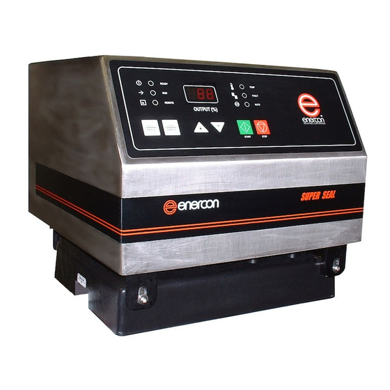
ENERCON SUPER SEAL Series Sealing Machine Manuals
Manuals and User Guides for ENERCON SUPER SEAL Series Sealing Machine. We have
1
ENERCON SUPER SEAL Series Sealing Machine manual available for free PDF download: Owner Reference Manual
ENERCON SUPER SEAL Series Owner Reference Manual (63 pages)
INDUCTION CAP SEALER
Brand:
ENERCON
| Category:
Food Saver
| Size: 2 MB
Table of Contents
Table of Contents
2
Section 1 - Introduction
4
Safety and Warnings
4
Safety Precautions
5
Understanding Induction Sealing
6
General
6
Material Variations
6
MULTIPLE LAYER LINERS (Figure 1)
6
SINGLE PIECE LINERS (Figure 2)
6
The Sealing Process
6
Unpacking and Inspection
7
Documentation
7
Optional Equipment
7
INDUCTION CAP SEALER FEATURES (Figure 3)
8
INFORMATION and SAFETY LABELS (Figure 4)
9
Section 2 - Installation
10
General
10
SCREW ADJUSTABLE MOUNT OPERATION (Figures 5 & 6)
10
FLOOR MOUNT INSTALLATION (Figure 7)
10
POWER SUPPLY MOUNTING YOKE INSTALLATION (Figures 8 & 9)
11
MOUNT PLACEMENT and INSTALLATION (Figures 10 & 11)
11
ATTACHING POWER SUPPLY to MOUNT (Figures 12 & 13)
12
MOBILE CART SYSTEM INSTALLATION (Figures 14 - 16)
12
System Alignment over Container
13
The Sealing Head and Surrounding Metal
13
CONTAINER PATH (Figure 17)
13
SEALING HEAD CENTERING (Figure 18)
14
SETTING the CONTAINER and SEALING HEAD GAP (Figure 19)
14
Detailed Sealing Head Alignment
14
STANDARD FLAT SEALING HEAD (Figure 20)
14
STANDARD TUNNEL SEALING HEAD (Figure 21)
14
DEEP TUNNEL SEALING HEAD (Figure 22)
15
ALIGNMENT and ADJUSTMENT "1" SEALING HEAD (Figure 23)
15
System Requirements
15
Temperature
15
Input Voltage Requirements
15
Grounding Requirements
15
BASIC UNIT - CABLE PROVISIONS (Figure 24)
16
Installation - Control Provisions
16
External Interlock
16
Using the Remote Start / Interlock Cable
16
Using the Defeat Connector
16
Stalled Bottle Defeat Connector
16
Loss of Sealing Indicator (Lsi)
17
Section 3 - Principles of Operation
18
General
18
CONTROL FUNCTIONS (Figure 25)
18
Sequence of Operation
19
LOCAL OPERATION (Figure 26)
19
Sealing Window Setup
19
Adjusting the Loss of Seal Indicator Alarm Setpoint
20
Remote Start Operation
22
Auto Control
22
Section 4 - Optional Equipment
22
General
23
Options Available
23
MOBILE CART (Figure 27)
23
STACK LIGHT (Figure 28)
23
Motion / Foil Detection Group
24
MOTION / FOIL DETECTION GROUP INTALLATION (Figure 29)
24
Motion Detection Only (Stalled Bottle)
24
STALLED BOTTLE SENSOR INSTALLATION (Figure 30)
25
STALLED BOTTLE SENSOR SETTINGS and ADJUSTMENTS (Figure 31)
25
Sensitivity Adjustment
25
Delay off
25
Delay on
25
Sensor Adjustment Procedure
25
FOIL LINER DETECTOR ONLY (Figure 32)
26
FOIL LINER DETECTOR INSTALLATION (Figure 33)
26
FOIL LINER DETECTOR CONTACTS CABLE (Figure 34)
26
FOIL LINER DETECTOR ALIGNMENT and ADJUSTMENT (Figure 35)
27
Beam Sensor Led Operation
27
BEAM SENSOR SENSITIVITY ADJUSTMENT (Figure 36)
27
Beam and Proximity Sensor Led Operation
27
PROXIMITY SENSOR SENSITIVITY ADJUSTMENT (Figure 37)
27
AUTO MODE (Figure 38)
28
Ejector System
28
EJECTOR INSTALLATION (Figure 39)
28
Spare Part Kits Avalable
29
Section 4 - Maintenance
30
General
30
Routine Inspection and Servicing
30
Visual Inspection
30
External Connections
30
Sealing Head Inspection
30
COOLING FANS and BASE PLATE INSPECTION (Figure 40)
30
Internal Connections
31
Maintenance Record
31
Section 5 - Troubleshooting
32
General
32
Remove/Install the Power Supply Cover
32
Front Panel 'F' Indications
32
F00 - over Current Trip
32
F02 and TEMP - CAP TRIP or OVER-TEMPERATURE (Figures 41 & 42)
33
F03 - Interlock Fault
35
F04 - under Voltage Trip
36
F05 - under Frequency Trip
36
Front Panel Blank
37
Fault
38
Pushbuttons Do Not Function
38
Output Stuck at Minimum
39
Auto Mode at Minimum
40
Display Flickers
40
Run Not Lit or Blinking
41
Inverter Ohm Check Procedure
42
Bridge Rectifier Ohm Check Procedure
42
Application Troubleshooting
43
Section 6 - Parts Lists
47
General
47
How to Use this Parts List
47
How to Order Parts
47
Shipping Instructions for Returns
47
SCREW ADJUSTABLE FLOOR MOUNT PARTS BREAKDOWN (Figure 43)
48
MOUNTING BRACKET PARTS BREAKDOWN (Figure 44)
49
STANDARD POWER SUPPLY PARTS BREAKDOWN (Figure 45)
50
CE POWER SUPPLY PARTS BREAKDOWN (Figure 46)
51
FAN and SEALING HEAD MOUNTING PARTS BREAKDOWN (Figure 47)
52
FRONT PANEL PARTS BREAKDOWN (Figure 48)
53
OPTIONAL STALLED BOTTLE SENSOR PARTS BREAKDOWN (Figure 49)
54
OPTIONAL FOIL LINER DETECTOR PARTS BREAKDOWN (Figure 50)
55
OPTIONAL STACK LIGHT PARTS BREAKDOWN (Figure 51)
56
OPTIONAL MOBILE CART PARTS BREAKDOWN (Figure 52)
57
Section 8 - Miscellaneous Maintenance Record
58
Production Information
60
Notes
62
Advertisement
Advertisement
Related Products
ENERCON SUPER SEAL 300
ENERCON SUPER SEAL 400
ENERCON SUPER SEAL 600
ENERCON AUTO JR.
ENERCON Categories
Food Saver
Industrial Equipment
Power Supply
Media Converter
More ENERCON Manuals
Login
Sign In
OR
Sign in with Facebook
Sign in with Google
Upload manual
Upload from disk
Upload from URL