Sign In
Upload
Manuals
Brands
Endress+Hauser Manuals
Measuring Instruments
Proline Promass S 500
Endress+Hauser Proline Promass S 500 Manuals
Manuals and User Guides for Endress+Hauser Proline Promass S 500. We have
2
Endress+Hauser Proline Promass S 500 manuals available for free PDF download: Operating Instructions Manual
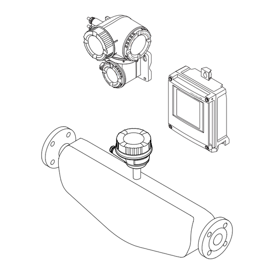
Endress+Hauser Proline Promass S 500 Operating Instructions Manual (314 pages)
Coriolis Flowmeter PROFINET over Ethernet-APL
Brand:
Endress+Hauser
| Category:
Measuring Instruments
| Size: 9 MB
Table of Contents
Table of Contents
3
About this Document
6
Document Function
6
Symbols
6
Safety Symbols
6
Electrical Symbols
6
Communication-Specific Symbols
6
Tool Symbols
7
Symbols for Certain Types of Information
7
Symbols in Graphics
7
Documentation
8
Registered Trademarks
8
Safety Instructions
9
Requirements for the Personnel
9
Intended Use
9
Workplace Safety
10
Operational Safety
10
Product Safety
10
Security
10
Device-Specific IT Security
11
Protecting Access Via Hardware Write Protection
11
Protecting Access Via a Password
11
Infrastructure Mode
12
Access Via Web Server
12
Access Via Service Interface (CDI-RJ45)
12
Product Description
13
Product Design
13
Proline 500 - Digital
13
Proline 500
13
Incoming Acceptance and Product
15
Identification
15
Incoming Acceptance
15
Product Identification
15
Transmitter Nameplate
16
Sensor Nameplate
18
Symbols on the Device
19
Storage and Transport
20
Storage Conditions
20
Transporting the Product
20
Measuring Devices Without Lifting Lugs
20
Measuring Devices with Lifting Lugs
21
Transporting with a Fork Lift
21
Packaging Disposal
21
Installation
21
Mounting Requirements
21
Installation Position
21
Inlet and Outlet Runs
23
Installation Dimensions
23
Environmental and Process Requirements
24
Thermal Insulation
24
Special Installation Instructions
25
Hygienic Compatibility
26
Weather Protection Cover
27
Installing the Measuring Instrument
28
Required Tools
28
Preparing the Measuring Instrument
28
Mounting the Measuring Device
28
Mounting the Transmitter Housing: Proline 500 - Digital
29
Mounting the Transmitter Housing: Proline 500
30
Wall Mounting
30
Turning the Transmitter Housing: Proline 500
31
Turning the Display Module: Proline 500
32
Post-Installation Check
33
Electrical Connection
34
Electrical Safety
34
Connecting Requirements
34
Required Tools
34
Requirements for Connection Cable
34
Terminal Assignment
38
Available Device Plugs
38
Device Plug Pin Assignment
39
Shielding and Grounding
39
Preparing the Measuring Device
40
Connecting the Measuring Instrument: Proline 500 - Digital
41
Connecting the Connecting Cable
41
Connecting the Transmitter
46
Integrating the Transmitter into a Network
49
Connecting the Measuring Instrument: Proline 500
50
Fitting the Connecting Cable
50
Connecting the Transmitter
54
Connecting Connector
54
Integrating the Transmitter into a Network
57
Potential Equalization
57
Requirements
57
Special Connection Instructions
58
Connection Examples
58
Current Output 4-20 Ma
58
Pulse/Frequency Output
59
Switch Output
59
Relay Output
60
Current Input
60
Status Input
60
Hardware Settings
61
Setting the Device Name
61
Activating the Default IP Address
63
Ensuring the Degree of Protection
64
Post-Connection Check
64
Endress+Hauser
65
Operation Options
66
Overview of Operation Options
66
Structure and Function of the Operating Menu
67
Structure of the Operating Menu
67
Operating Philosophy
68
Access to Operating Menu Via Local Display
69
Operational Display
69
Status Signals
69
Display Area
70
Navigation View
71
Navigation Path
71
Locking Procedure
72
Editing View
73
Numeric Editor
73
Text Editor
73
Operating Elements
75
Opening the Context Menu
75
Navigating and Selecting from List
77
Calling the Parameter Directly
77
Calling up Help Text
78
Changing the Parameters
78
User Roles and Related Access Authorization
79
Disabling Write Protection Via Access Code
79
Enabling and Disabling the Keypad Lock
80
Access to Operating Menu Via Web Browser
80
Function Range
80
Requirements
81
Connecting the Device
82
Logging on
84
User Interface
85
Function Row
85
Navigation Area
85
Disabling the Web Server
86
Logging out
86
Access to the Operating Menu Via the Operating Tool
87
Connecting the Operating Tool
87
Service Interface
88
Fieldcare
90
Devicecare
91
Simatic Pdm
92
System Integration
93
Overview of Device Description Files
93
Current Version Data for the Device
93
Operating Tools
93
Device Master File (GSD)
93
File Name of the Manufacturer-Specific Device Master File (GSD)
94
File Name of the PA Profile Device Master File (GSD)
94
Cyclic Data Transmission
95
Overview of the Modules
95
Description of the Modules
96
Binary Output Module
103
Data Structure
104
Status Coding
105
Factory Setting
106
System Redundancy S2
107
Commissioning
108
Post-Mounting and Post-Connection Check
108
Switching on the Measuring Device
108
Connecting Via Fieldcare
108
Setting the Operating Language
108
Configuring the Measuring Instrument
109
Defining the Tag Name
110
Displaying the Communication Interface
110
Parameter Overview with Brief Description
111
Setting the System Units
112
Selecting and Setting the Medium
115
Configuration of the Analog Inputs
116
Displaying the I/O Configuration
119
Configuring the Current Input
120
Configuring the Status Input
121
Configuring the Current Output
122
10.5.10 Configuring the Pulse/Frequency/Switch Output
125
10.5.11 Configuring the Relay Output
133
10.5.12 Configuring the Local Display
136
10.5.13 Configuring the Low Flow Cut off
140
10.5.14 Configuring Partially Filled Pipe Detection
141
Advanced Settings
142
Using the Parameter to Enter the Access Code
143
Calculated Process Variables
143
Carrying out a Sensor Adjustment
145
Density Adjustment
145
Configuring the Totalizer
151
Carrying out Additional Display Configurations
153
Endress+Hauser
153
WLAN Configuration
159
Viscosity Application Package
161
Concentration Measurement
161
Application Package
161
Petroleum Application Package
161
Heartbeat Technology Application Package
162
10.6.11 Configuration Management
162
Function Scope of the "Configuration Management" Parameter
163
10.6.12 Using Parameters for Device Administration
163
Simulation
164
Protecting Settings from Unauthorized Access
167
Write Protection Via Access Code
167
Write Protection Via Write Protection Switch
169
Operation
171
Reading off the Device Locking Status
171
Adjusting the Operating Language
171
Configuring the Display
171
Reading Measured Values
171
Measured Variables" Submenu
172
Totalizer
174
Input Values" Submenu
175
Output Values
176
Adapting the Measuring Device to the Process Conditions
178
Performing a Totalizer Reset
178
Function Scope of "Control Totalizer" Parameter
179
Function Range of "Reset All Totalizers" Parameter
179
Displaying the Measured Value History
180
Gas Fraction Handler
183
Measurement Mode" Submenu
184
Medium Index" Submenu
184
Diagnostics and Troubleshooting
186
General Troubleshooting
186
Diagnostic Information Via Light Emitting Diodes
188
Transmitter
188
Sensor Connection Housing
190
Diagnostic Information on Local Display
192
Diagnostic Message
192
Diagnostic Information
193
Calling up Remedial Measures
194
Diagnostic Information in the Web Browser
194
Diagnostic Options
194
Calling up Remedy Information
195
Diagnostic Information in Fieldcare or Devicecare
195
Diagnostic Options
195
Calling up Remedy Information
196
Adapting the Diagnostic Information
197
Adapting the Diagnostic Behavior
197
Overview of Diagnostic Information
198
Diagnostic of Sensor
199
Diagnostic of Electronic
211
Diagnostic of Configuration
239
Diagnostic of Process
250
Pending Diagnostic Events
264
Diagnostics List
265
12.10 Event Logbook
265
12.10.1 Reading out the Event Logbook
265
12.10.2 Filtering the Event Logbook
266
12.10.3 Overview of Information Events
266
12.11 Resetting the Measuring Device
268
12.11.1 Function Range of "Device Reset" Parameter
268
12.12 Device Information
268
12.13 Firmware History
270
Maintenance
271
Maintenance Work
271
Exterior Cleaning
271
Internal Cleaning
271
Measuring and Test Equipment
271
Endress+Hauser Services
271
Repair
272
General Notes
272
Repair and Conversion Concept
272
Notes for Repair and Conversion
272
Spare Parts
272
Endress+Hauser Services
272
Return
272
Disposal
273
Removing the Measuring Device
273
Disposing of the Measuring Device
273
Accessories
274
Device-Specific Accessories
274
For the Transmitter
274
For the Sensor
275
Communication-Specific Accessories
275
Service-Specific Accessories
276
System Components
277
Technical Data
278
Application
278
Function and System Design
278
Input
279
Direct Measured Variables
279
Output
281
Output Signal
281
Local Display
285
Web Browser
285
Light Emitting Diodes (LED)
286
Power Supply
287
Performance Characteristics
288
Reference Operating Conditions
288
Design Fundamentals
288
Zero Point Stability
289
Flow Values
289
Mounting
292
Environment
292
Process
294
16.10 Mechanical Construction
295
Transmitter Housing
296
16.11 User Interface
298
Display Elements
299
Historom Data Management
301
16.12 Certificates and Approvals
302
16.13 Application Packages
304
Heartbeat Verification
305
Heartbeat Monitoring
305
16.14 Accessories
306
16.15 Supplemental Documentation
306
Technical Information
306
Description of Device Parameters
306
Special Documentation
307
Installation Instructions
307
Index
308
Advertisement
Endress+Hauser Proline Promass S 500 Operating Instructions Manual (282 pages)
PROFINET Coriolis flowmeter
Brand:
Endress+Hauser
| Category:
Measuring Instruments
| Size: 12 MB
Table of Contents
Table of Contents
3
About this Document
6
Document Function
6
Symbols
6
Safety Symbols
6
Electrical Symbols
6
Communication Symbols
6
Tool Symbols
7
Symbols for Certain Types of Information
7
Symbols in Graphics
7
Documentation
8
Standard Documentation
8
Supplementary Device-Dependent Documentation
8
Registered Trademarks
8
Safety Instructions
10
Requirements for the Personnel
10
Designated Use
10
Workplace Safety
11
Operational Safety
11
Product Safety
11
IT Security
12
Device-Specific IT Security
12
Protecting Access Via Hardware Write Protection
12
Protecting Access Via a Password
12
Access Via Web Server
13
Access Via Service Interface (CDI-RJ45)
14
Product Description
15
Product Design
15
Proline 500 - Digital
15
Proline 500
15
Incoming Acceptance and Product
17
Identification
17
Incoming Acceptance
17
Product Identification
17
Transmitter Nameplate
18
Sensor Nameplate
20
Symbols on Measuring Device
21
Storage and Transport
22
Storage Conditions
22
Transporting the Product
22
Measuring Devices Without Lifting Lugs
22
Measuring Devices with Lifting Lugs
23
Transporting with a Fork Lift
23
Packaging Disposal
23
Installation
23
Installation Conditions
23
Mounting Position
23
Environment and Process Requirements
26
Special Mounting Instructions
27
Mounting the Measuring Device
29
Required Tools
29
Preparing the Measuring Device
29
Mounting the Measuring Device
30
Mounting the Transmitter Housing: Proline 500 - Digital
30
Mounting the Transmitter Housing: Proline 500
32
Turning the Transmitter Housing: Proline 500
33
Turning the Display Module: Proline 500
33
Post-Installation Check
34
Electrical Connection
35
Connection Conditions
35
Required Tools
35
Requirements for Connecting Cable
35
Terminal Assignment
39
Device Plugs Available
39
Pin Assignment of Device Plug
40
Preparing the Measuring Device
40
Connecting the Measuring Device: Proline 500 - Digital
41
Connecting the Connecting Cable
41
Connecting the Transmitter
46
Integrating the Transmitter into a Network
49
Connecting the Measuring Device: Proline 500
51
Connecting the Connecting Cable
51
Connecting the Transmitter
54
Integrating the Transmitter into a Network
57
Ensuring Potential Equalization
58
Requirements
58
Special Connection Instructions
59
Connection Examples
59
Hardware Settings
62
Setting the Device Name
62
Activating the Default IP Address
65
Ensuring the Degree of Protection
66
Post-Connection Check
67
Operation Options
68
Overview of Operation Options
68
Structure and Function of the Operating
69
Structure of the Operating Menu
69
Operating Philosophy
70
Access to the Operating Menu Via the Local Display
71
Operational Display
71
Navigation View
72
Editing View
74
Operating Elements
76
Opening the Context Menu
76
Navigating and Selecting from List
78
Calling the Parameter Directly
78
Calling up Help Text
79
Changing the Parameters
79
User Roles and Related Access Authorization
80
Disabling Write Protection Via Access
80
Code
80
Enabling and Disabling the Keypad
81
Access to the Operating Menu Via the Web Browser
81
Function Range
81
Prerequisites
82
Establishing a Connection
83
Logging on
85
User Interface
86
Disabling the Web Server
87
Logging out
88
Access to the Operating Menu Via the Operating Tool
88
Connecting the Operating Tool
88
Fieldcare
92
Devicecare
93
System Integration
94
Overview of Device Description Files
94
Current Version Data for the Device
94
Operating Tools
94
Device Master File (GSD)
95
File Name of the Device Master File (GSD)
95
Cyclic Data Transmission
96
Overview of the Modules
96
Description of the Modules
96
Status Coding
104
Factory Setting
105
Startup Configuration
106
System Redundancy S2
107
Commissioning
108
Function Check
108
Switching on the Measuring Device
108
Connecting Via Fieldcare
108
Setting the Operating Language
108
Configuring the Measuring Device
109
Defining the Tag Name
110
Setting the System Units
110
10.5.3 Displaying the Communication
112
Interface
114
Selecting and Setting the Medium
114
Displaying the I/O Configuration
114
Configuring the Current Input
115
Configuring the Status Input
116
Configuring the Current Output
117
Configuring the Pulse/Frequency
120
Switch Output
120
10.5.10 Configuring the Relay Output
127
10.5.11 Configuring the Local Display
129
10.5.12 Configuring the Low Flow Cut off
132
Configuring the Partial Filled Pipe
133
Detection
133
Advanced Settings
134
Using the Parameter to Enter the Access Code
135
Calculated Values
135
Carrying out a Sensor Adjustment
136
Configuring the Totalizer
137
Carrying out Additional Display Configurations
139
WLAN Configuration
142
Configuration Management
144
Using Parameters for Device Administration
145
Simulation
147
Protecting Settings from Unauthorized
150
Access
150
Write Protection Via Write Protection
151
Switch
151
Operation
154
Reading the Device Locking Status
154
Adjusting the Operating Language
154
Configuring the Display
154
Reading Measured Values
154
Measured Variables" Submenu
155
Totalizer
156
Input Values" Submenu
157
Output Values
158
Adapting the Measuring Device to the Process
160
Conditions
160
Performing a Totalizer Reset
160
Function Scope of the "Control Totalizer" Parameter
161
Function Scope of the "Reset All Totalizers" Parameter
161
Showing Data Logging
162
Diagnostics and Troubleshooting
166
General Troubleshooting
166
Diagnostic Information Via Light Emitting
169
Diodes
169
Transmitter
169
Sensor Connection Housing
171
Diagnostic Information on Local Display
173
Diagnostic Message
173
Calling up Remedial Measures
175
Diagnostic Information in the Web Browser
175
Diagnostic Options
175
Calling up Remedy Information
176
Diagnostic Information in Fieldcare or Devicecare
176
Diagnostic Options
176
Calling up Remedy Information
177
Adapting the Diagnostic Information
178
Adapting the Diagnostic Behavior
178
Overview of Diagnostic Information
181
Diagnostic of Sensor
181
Diagnostic of Electronic
188
Diagnostic of Configuration
205
Diagnostic of Process
218
Pending Diagnostic Events
232
Diagnostic List
232
12.10 Event Logbook
233
Reading out the Event Logbook
233
12.10.2 Filtering the Event Logbook
234
12.10.3 Overview of Information Events
234
12.11 Resetting the Measuring Device
235
12.11.1 Function Scope of the "Device Reset" Parameter
235
12.12 Device Information
236
12.13 Firmware History
238
Maintenance
239
Maintenance Tasks
239
Exterior Cleaning
239
Interior Cleaning
239
Measuring and Test Equipment
239
Endress+Hauser Services
239
Repair
240
General Notes
240
Repair and Conversion Concept
240
Notes for Repair and Conversion
240
Spare Parts
240
Endress+Hauser Services
240
Return
240
Disposal
240
Removing the Measuring Device
240
Disposing of the Measuring Device
241
Accessories
242
Device-Specific Accessories
242
For the Transmitter
242
For the Sensor
243
Communication-Specific Accessories
243
Service-Specific Accessories
244
System Components
245
Technical Data
246
Application
246
Function and System Design
246
Input
247
Output
249
Power Supply
254
Performance Characteristics
255
Installation
259
Environment
259
Process
260
16.10 Mechanical Construction
262
16.11 Human Interface
266
16.12 Certificates and Approvals
269
16.13 Application Packages
271
16.14 Accessories
273
16.15 Supplementary Documentation
273
Index
275
Advertisement
Related Products
Endress+Hauser Cerabar S PMP75
Endress+Hauser Cerabar S PMP7
Endress+Hauser Smartec S CLD132
Endress+Hauser Proline Promass S 300
Endress+Hauser SpectraSensors SS2100r
Endress+Hauser SpectraSensors SS2100
Endress+Hauser Liquiphant S FDL61
Endress+Hauser SS500
Endress+Hauser SS2000XP
Endress+Hauser SS3000
Endress+Hauser Categories
Measuring Instruments
Transmitter
Radar
Switch
Accessories
More Endress+Hauser Manuals
Login
Sign In
OR
Sign in with Facebook
Sign in with Google
Upload manual
Upload from disk
Upload from URL