Sign In
Upload
Manuals
Brands
Endress+Hauser Manuals
Measuring Instruments
Proline Promass Q 500
Endress+Hauser Proline Promass Q 500 Manuals
Manuals and User Guides for Endress+Hauser Proline Promass Q 500. We have
2
Endress+Hauser Proline Promass Q 500 manuals available for free PDF download: Operating Instructions Manual
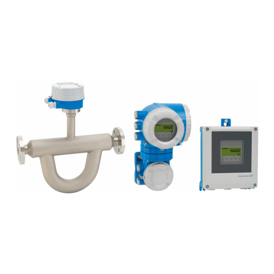
Endress+Hauser Proline Promass Q 500 Operating Instructions Manual (270 pages)
Coriolis Flowmeter HART
Brand:
Endress+Hauser
| Category:
Measuring Instruments
| Size: 10 MB
Table of Contents
Table of Contents
3
About this Document
6
Document Function
6
Symbols
6
Safety Symbols
6
Electrical Symbols
6
Communication-Specific Symbols
6
Tool Symbols
7
Symbols for Certain Types of Information
7
Symbols in Graphics
7
Documentation
8
Registered Trademarks
8
Safety Instructions
9
Requirements for the Personnel
9
Intended Use
9
Workplace Safety
10
Operational Safety
10
Product Safety
10
Security
10
Device-Specific IT Security
11
Protecting Access Via Hardware Write Protection
11
Protecting Access Via a Password
11
Infrastructure Mode
12
Access Via Web Server
12
Access Via OPC-UA
12
Access Via Service Interface (CDI-RJ45)
12
Product Description
14
Product Design
14
Proline 500 - Digital
14
Proline 500
14
Incoming Acceptance and Product
16
Identification
16
Incoming Acceptance
16
Product Identification
16
Incoming Acceptance and Product Identification
17
Transmitter Nameplate
17
Sensor Nameplate
19
Symbols on the Device
20
Storage and Transport
21
Storage Conditions
21
Transporting the Product
21
Measuring Devices Without Lifting Lugs
21
Measuring Devices with Lifting Lugs
22
Transporting with a Fork Lift
22
Packaging Disposal
22
Installation
22
Mounting Requirements
22
Installation Position
22
Inlet and Outlet Runs
24
Installation Dimensions
24
Environmental and Process Requirements
25
Thermal Insulation
25
Special Installation Instructions
26
Hygienic Compatibility
27
Weather Protection Cover
29
Installing the Measuring Instrument
30
Required Tools
30
Preparing the Measuring Instrument
30
Mounting the Measuring Device
31
Mounting the Transmitter Housing: Proline 500 - Digital
31
Wall Mounting
32
Drill the Holes
32
Mounting the Transmitter Housing: Proline 500
33
Turning the Transmitter Housing: Proline 500
34
Turning the Display Module: Proline 500
34
Post-Installation Check
35
Electrical Connection
36
Electrical Safety
36
Connecting Requirements
36
Required Tools
36
Requirements for Connection Cable
36
Terminal Assignment
41
Preparing the Measuring Device
41
Connecting the Measuring Instrument: Proline 500 - Digital
43
Connecting the Connecting Cable
43
Connecting the Signal Cable and the Supply Voltage Cable
48
Connecting the Measuring Instrument: Proline 500
50
Fitting the Connecting Cable
50
Connecting the Signal Cable and the Supply Voltage Cable
55
Potential Equalization
57
Requirements
57
Special Connection Instructions
58
Connection Examples
58
HART Input
59
Current Output 4-20 Ma
59
Pulse/Frequency Output
60
Switch Output
60
Relay Output
61
Current Input
61
Ensuring the Degree of Protection
62
Post-Connection Check
62
Endress+Hauser
63
Operation Options
64
Overview of Operation Options
64
Structure and Function of the Operating Menu
65
Structure of the Operating Menu
65
Operating Philosophy
66
Access to Operating Menu Via Local Display
67
Operational Display
67
Status Signals
67
Display Area
68
Navigation View
70
Navigation Path
70
Locking Procedure
71
Editing View
72
Numeric Editor
72
Text Editor
72
Operating Elements
74
Opening the Context Menu
74
Navigating and Selecting from List
76
Calling the Parameter Directly
76
Calling up Help Text
77
Changing the Parameters
77
User Roles and Related Access Authorization
78
Disabling Write Protection Via Access Code
78
Enabling and Disabling the Keypad
79
Access to Operating Menu Via Web Browser
79
Function Range
79
Requirements
80
Connecting the Device
81
Enter the Password
82
Starting the Web Browser
82
Logging on
83
User Interface
84
Function Row
84
Navigation Area
84
Disabling the Web Server
85
Logging out
85
Access to the Operating Menu Via the Operating Tool
86
Connecting the Operating Tool
86
Service Interface
87
Field Xpert SFX350, SFX370
90
Fieldcare
90
Devicecare
91
AMS Device Manager
91
Field Communicator 475
92
Simatic Pdm
92
System Integration
93
Overview of Device Description Files
93
Current Version Data for the Device
93
Operating Tools
93
Measured Variables Via HART Protocol
94
Device Variables
98
Other Settings
99
Parameter Overview with Brief Description
99
Commissioning
102
Post-Mounting and Post-Connection Check
102
Switching on the Measuring Device
102
Setting the Operating Language
102
Configuring the Measuring Instrument
102
Defining the Tag Name
104
Setting the System Units
104
Selecting and Setting the Medium
107
Displaying the I/O Configuration
109
Configuring the Current Input
109
Configuring the Status Input
111
Configuring the Current Output
111
Configuring the Pulse/Frequency
116
Switch Output
116
Configuring the Relay Output
125
10.4.10 Configuring the Double Pulse Output
128
10.4.11 Configuring the Local Display
129
10.4.12 Configuring the Low Flow Cut off
135
10.4.13 Configuring Partially Filled Pipe Detection
136
Advanced Settings
137
Using the Parameter to Enter the Access Code
138
Calculated Process Variables
138
Carrying out a Sensor Adjustment
139
Density Adjustment
140
Configuring the Totalizer
146
Carrying out Additional Display Configurations
148
Endress+Hauser
149
WLAN Configuration
155
Configuration Management
156
Function Scope of the "Configuration Management" Parameter
157
Using Parameters for Device Administration
157
Simulation
159
Protecting Settings from Unauthorized Access
162
Write Protection Via Access Code
162
Write Protection Via Write Protection Switch
163
Operation
166
Reading off the Device Locking Status
166
Adjusting the Operating Language
166
Configuring the Display
166
Reading off Measured Values
166
Measured Variables" Submenu
167
Endress+Hauser
167
Totalizer" Submenu
178
Input Values" Submenu
178
Output Values
180
Adapting the Measuring Device to the Process Conditions
182
Performing a Totalizer Reset
182
Function Scope of "Control Totalizer" Parameter
184
Function Range of "Reset All Totalizers" Parameter
184
Displaying the Measured Value History
184
Gas Fraction Handler
188
Measurement Mode" Submenu
188
Medium Index" Submenu
189
Diagnostics and Troubleshooting
190
General Troubleshooting
190
Diagnostic Information Via Light Emitting Diodes
193
Transmitter
193
Sensor Connection Housing
195
Diagnostic Information on Local Display
196
Diagnostic Message
196
Diagnostic Information
197
Calling up Remedial Measures
198
Diagnostic Information in the Web Browser
199
Diagnostic Options
199
Calling up Remedy Information
200
Diagnostic Information in Fieldcare or
201
Diagnostic Options
201
Calling up Remedy Information
202
Adapting the Diagnostic Information
203
Adapting the Diagnostic Behavior
203
Adapting the Status Signal
203
Overview of Diagnostic Information
205
Pending Diagnostic Events
210
Diagnostics List
210
12.10 Event Logbook
212
12.10.1 Reading out the Event Logbook
212
12.10.2 Filtering the Event Logbook
212
12.10.3 Overview of Information Events
213
12.11 Resetting the Measuring Device
215
12.11.1 Function Range of "Device Reset" Parameter
215
12.12 Device Information
216
12.13 Firmware History
218
12.14 Device History and Compatibility
219
Maintenance
220
Maintenance Work
220
Exterior Cleaning
220
Measuring and Test Equipment
220
Endress+Hauser Services
220
Repair
221
General Notes
221
Repair and Conversion Concept
221
Notes for Repair and Conversion
221
Spare Parts
221
Endress+Hauser Services
221
Return
221
Disposal
222
Removing the Measuring Device
222
Disposing of the Measuring Device
222
Accessories
223
Device-Specific Accessories
223
For the Transmitter
223
For the Sensor
224
Communication-Specific Accessories
224
Service-Specific Accessories
225
System Components
226
Technical Data
227
Application
227
Function and System Design
227
Input
228
Direct Measured Variables
228
Output
230
Output Signal
230
Current Output 4 to 20 Ma
231
Local Display
235
Web Browser
236
Light Emitting Diodes (LED)
236
Power Supply
236
Performance Characteristics
238
Mounting
243
Environment
243
Internal Cleaning
244
Process
245
Pressure-Temperature Ratings
245
Flow Limit
246
16.10 Custody Transfer
248
16.11 Mechanical Construction
248
Transmitter Housing
249
Connecting Cables
250
Measuring Tubes
251
Process Connections
251
16.12 User Interface
252
Historom Data Management
254
16.13 Certificates and Approvals
255
16.14 Application Packages
258
Heartbeat Verification
259
Heartbeat Monitoring
259
16.15 Accessories
260
16.16 Supplemental Documentation
260
Technical Information
261
Description of Device Parameters
261
Special Documentation
262
Installation Instructions
262
Advertisement
Endress+Hauser Proline Promass Q 500 Operating Instructions Manual (280 pages)
Brand:
Endress+Hauser
| Category:
Measuring Instruments
| Size: 8 MB
Table of Contents
Table of Contents
3
Document Information
6
Document Function
6
Symbols Used
6
Safety Symbols
6
Electrical Symbols
6
Communication Symbols
6
Tool Symbols
7
Symbols for Certain Types of Information
7
Symbols in Graphics
7
Documentation
8
Standard Documentation
8
Supplementary Device-Dependent Documentation
8
Registered Trademarks
9
Basic Safety Instructions
10
Requirements for the Personnel
10
Designated Use
10
Workplace Safety
11
Operational Safety
11
Product Safety
11
Security
12
Device-Specific IT Security
12
Protecting Access Via Hardware Write Protection
12
Protecting Access Via a Password
12
Access Via Fieldbus
13
Access Via Web Server
13
Product Description
14
Product Design
14
Proline 500 - Digital
14
Proline 500
14
Incoming Acceptance and Product
16
Identification
16
Incoming Acceptance
16
Product Identification
17
Transmitter Nameplate
17
Sensor Nameplate
19
Symbols on Measuring Device
20
Storage and Transport
21
Storage Conditions
21
Transporting the Product
21
Measuring Devices Without Lifting Lugs
21
Measuring Devices with Lifting Lugs
22
Transporting with a Fork Lift
22
Packaging Disposal
22
Installation
22
Installation Conditions
22
Mounting Position
22
Requirements from Environment and Process
24
Special Mounting Instructions
25
Mounting the Measuring Device
28
Required Tools
28
Preparing the Measuring Device
28
Mounting the Transmitter Housing: Proline 500 - Digital
29
Mounting the Transmitter Housing: Proline 500
30
Turning the Transmitter Housing: Proline 500
32
Turning the Display Module: Proline 500
33
Post-Installation Check
33
Electrical Connection
34
Connection Conditions
34
Required Tools
34
Requirements for Connecting Cable
34
Terminal Assignment
37
Device Plugs Available
37
Pin Assignment of Device Plug
38
Preparing the Measuring Device
38
Connecting the Measuring Device: Proline 500 - Digital
39
Connecting the Connecting Cable
39
Connecting the Signal Cable and the Supply Voltage Cable
44
Connecting the Measuring Device: Proline 500
46
Connecting the Connecting Cable
46
Connecting the Signal Cable and the Supply Voltage Cable
50
Ensure Potential Equalization
52
Requirements
52
Special Connection Instructions
53
Connection Examples
53
Hardware Settings
56
Setting the Device Address
56
Ensuring the Degree of Protection
57
Post-Connection Check
58
Operation Options
59
Overview of Operation Options
59
Structure and Function of the Operating Menu
60
Structure of the Operating Menu
60
Operating Philosophy
61
Access to the Operating Menu Via the Local Display
62
Operational Display
62
Navigation View
64
Editing View
66
Operating Elements
67
Opening the Context Menu
68
Navigating and Selecting from List
70
Calling the Parameter Directly
70
Calling up Help Text
71
Changing the Parameters
72
User Roles and Related Access Authorization
73
Disabling Write Protection Via Access
73
Code
73
Enabling and Disabling the Keypad
73
Access to the Operating Menu Via the Web Browser
74
Function Range
74
Prerequisites
74
Establishing a Connection
76
Logging on
78
User Interface
79
Disabling the Web Server
80
Logging out
80
Access to the Operating Menu Via the Operating Tool
80
Connecting the Operating Tool
81
Fieldcare
83
Devicecare
84
Simatic Pdm
85
System Integration
86
Overview of Device Description Files
86
Current Version Data for the Device
86
Operating Tools
86
Device Master File (GSD)
86
Manufacturer-Specific GSD
87
Profile GSD
87
Compatibility with Earlier Model
88
Automatic Identification
88
Setting)
88
Manual Setting
88
Replacing the Measuring Devices Without Changing the GSD File or Restarting the Controller
88
Using the GSD Modules of the Previous Model
89
Using the CONTROL_BLOCK Module
89
In the Previous Model
89
Cyclic Data Transmission
91
Block Model
91
Description of the Modules
91
Commissioning
98
Function Check
98
Switching on the Measuring Device
98
Connecting Via Fieldcare
98
Configuring the Device Address Via Software
98
PROFIBUS Network
98
Setting the Operating Language
98
Configuring the Measuring Device
99
Defining the Tag Name
100
Setting the System Units
101
Selecting and Setting the Medium
104
Configuring Communication
105
Interface
105
Configuring the Analog Inputs
107
Displaying the I/O Configuration
108
Configuring the Current Input
109
Configuring the Status Input
110
Configuring the Current Output
110
10.6.10 Configuring the Pulse/Frequency/Switch Output
113
10.6.11 Configuring the Relay Output
122
10.6.12 Configuring the Double Pulse Output
124
10.6.13 Configuring the Local Display
125
10.6.14 Configuring the Low Flow Cut off
128
Configuring the Partial Filled Pipe
129
Advanced Settings
130
Calculated Values
131
Carrying out a Sensor Adjustment
132
Configuring the Totalizer
133
Carrying out Additional Display Configurations
135
WLAN Configuration
138
Configuration Management
139
Using Parameters for Device Administration
140
Simulation
142
Protecting Settings from Unauthorized
145
Access
145
Write Protection Via Access Code
145
Write Protection Via Write Protection
146
Switch
146
Operation
149
Reading the Device Locking Status
149
Adjusting the Operating Language
149
Configuring the Display
149
Reading Measured Values
149
Measured Variables" Submenu
150
Totalizer
151
Input Values" Submenu
152
Output Values
153
Adapting the Measuring Device to the Process
156
Conditions
156
Performing a Totalizer Reset
156
Showing Data Logging
157
Diagnostics and Troubleshooting
160
General Troubleshooting
160
Diagnostic Information Via Light Emitting
163
Diodes
163
Transmitter
163
Sensor Connection Housing
164
Diagnostic Information on Local Display
166
Diagnostic Message
166
Calling up Remedial Measures
168
Diagnostic Information in the Web Browser
168
Diagnostic Options
168
Calling up Remedy Information
169
Diagnostic Information in Devicecare or
169
Fieldcare
169
Diagnostic Options
169
Calling up Remedy Information
170
Adapting the Diagnostic Information
171
Adapting the Diagnostic Behavior
171
Overview of Diagnostic Information
173
Diagnostic of Sensor
174
Diagnostic of Electronic
182
Diagnostic of Configuration
204
Diagnostic of Process
217
Pending Diagnostic Events
230
Diagnostic List
231
12.10 Event Logbook
232
12.10.1 Event History
232
12.10.2 Filtering the Event Logbook
233
12.10.3 Overview of Information Events
233
12.11 Resetting the Measuring Device
234
12.11.1 Function Scope of the "Device Reset" Parameter
235
12.12 Device Information
235
12.13 Firmware History
237
Maintenance
238
Maintenance Tasks
238
Exterior Cleaning
238
Measuring and Test Equipment
238
Endress+Hauser Services
238
Repairs
239
General Notes
239
Repair and Conversion Concept
239
Notes for Repair and Conversion
239
Spare Parts
239
Endress+Hauser Services
239
Return
239
Disposal
240
Removing the Measuring Device
240
Disposing of the Measuring Device
240
Accessories
241
Device-Specific Accessories
241
For the Transmitter
241
For the Sensor
242
Service-Specific Accessories
242
System Components
242
Technical Data
244
Application
244
Function and System Design
244
Input
245
Output
247
Power Supply
252
Performance Characteristics
253
Installation
257
Environment
258
Process
258
16.10 Mechanical Construction
261
16.11 Operability
264
16.12 Certificates and Approvals
267
16.13 Application Packages
269
16.14 Accessories
270
16.15 Supplementary Documentation
270
Index
273
Advertisement
Related Products
Endress+Hauser Proline Promass Q 300
Endress+Hauser Liquitrend QMW43
Endress+Hauser analytikjena qTOWER3 84 auto
Endress+Hauser QWX43
Endress+Hauser QG2000
Endress+Hauser Proline Promass 83
Endress+Hauser Proline Promass 80H
Endress+Hauser Proline Promass 83H
Endress+Hauser Proline Promass 80E
Endress+Hauser Proline Promass 83E
Endress+Hauser Categories
Measuring Instruments
Transmitter
Radar
Switch
Accessories
More Endress+Hauser Manuals
Login
Sign In
OR
Sign in with Facebook
Sign in with Google
Upload manual
Upload from disk
Upload from URL