Sign In
Upload
Manuals
Brands
Enclustra Manuals
Control Unit
ME-XU9-4CG-1E-D11E
User Manuals: Enclustra ME-XU9-4CG-1E-D11E Module
Manuals and User Guides for Enclustra ME-XU9-4CG-1E-D11E Module. We have
2
Enclustra ME-XU9-4CG-1E-D11E Module manuals available for free PDF download: User Manual
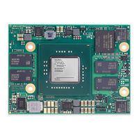
Enclustra ME-XU9-4CG-1E-D11E User Manual (61 pages)
SoC Module
Brand:
Enclustra
| Category:
Computer Hardware
| Size: 3 MB
Table of Contents
Table of Contents
3
Rohs
6
Safety Recommendations and Warnings
6
Disposal and WEEE
6
Overview
6
Warranty
6
Introduction
6
General
6
Electromagnetic Compatibility
7
Features
7
Electrostatic Discharge
7
Deliverables
8
Accessories
8
Reference Design
8
Enclustra Build Environment
8
Petalinux BSP
8
Mercury+ ST1 Base Board
9
Enclustra Heat Sink
9
Mercury+ PE3 Base Board
9
Mercury+ PE1 Base Board
9
Xilinx Tool Support
10
Module Description
11
Block Diagram
11
Hardware Block Diagram
11
Standard Module Configurations
12
EN-Numbers and Part Names
12
Product Model Fields
12
Module Configuration and Product Models
12
Module Label
13
Numbers and Part Names
13
Top and Bottom Views
14
Top View
14
Bottom View
14
Module Top View
14
Module Bottom View
14
Top and Bottom Assembly Drawings
15
Top Assembly Drawing
15
Bottom Assembly Drawing
15
Module Top Assembly Drawing
15
Module Bottom Assembly Drawing
15
Module Footprint
16
Module Footprint - Top View
16
Module Connector Types
17
Mechanical Data
17
Module Connector
17
Pin Numbering for the Module Connector
18
User I/O
18
Pinout
18
I/O Pin Exceptions
19
User I/Os
19
I/O Pin Exceptions - PERST
20
I/O Pin Exceptions - Level Shifters
20
Differential I/Os
21
I/O Banks
21
I/O Banks
22
VCC_IO Usage
22
Signal Terminations
23
Multiplexed I/O (MIO) Pins
24
MIO Pins Connections Overview
24
Analog Inputs
25
Multi-Gigabit Transceiver (MGT)
25
System Monitor (PL) Parameters
25
MGT Pairs
26
Power
27
Power Generation Overview
28
Generated Power Supplies
28
Module Power Status and Control Pins
29
Power Enable/Power Good
29
Voltage Supply Inputs
29
Voltage Supply Outputs
30
Power Consumption
30
Heat Dissipation
30
Voltage Monitoring
31
Heat Sink Type
31
Voltage Monitoring Outputs
31
Module Clock Resources
32
Reset
32
Clock Generation
32
Leds
33
Ddr4 Sdram (Ps)
33
Reset Resources
33
User Leds
33
Status Leds
33
Parameters
34
DDR4 SDRAM (PS) Types
34
Signal Description
34
Termination
34
DDR4 SDRAM Type
34
Ddr4 Sdram (Pl)
35
DDR4 SDRAM (PS) Parameters
35
DDR4 SDRAM Type
36
Signal Description
36
Termination
36
Parameters
36
DDR4 SDRAM (PL) Types
36
DDR4 SDRAM (PL) Parameters
37
QSPI Flash
37
Signal Description
37
QSPI Flash Type
37
Configuration
38
QSPI Flash Corruption Risk
38
Emmc Flash
38
Emmc Flash Type
38
Gigabit Ethernet Phys Type
39
Ethernet PHY Type
39
Dual Gigabit Ethernet
39
SD Card
39
Signal Description
39
External Connectivity
40
MDIO Address
40
PHY Configuration
40
USB1/ETH1 Selection
40
Gigabit Ethernet Phys Configuration - RGMII Delays
41
Gigabit Ethernet Phys Configuration - Bootstraps
41
USB PHY Type
41
Usb 2.0
41
RGMII Delays Configuration
41
Signal Description
42
Usb 3.0
42
USB 2.0 PHY Type
42
Display Port
43
Real-Time Clock (RTC)
43
USB 3.0 Implementation Example
43
Secure EEPROM
44
EEPROM Type
44
Mpsoc Configuration Pins
45
Configuration Signals
45
Device Configuration
45
Module Connector C Detection
46
Pull-Up During Configuration
46
Pull-Up During Configuration (PUDC) and Power-On Reset Delay Override (PORSEL)
46
VCC_IO Pins
46
Power-On Reset Delay Override
47
Boot Mode
47
Jtag
48
JTAG on Module Connector
48
Boot Modes
48
JTAG Interface - PL and PS Access and Debug
49
JTAG Boot Mode
49
External Connectivity
49
JTAG Boot Mode Resistor - Assembly Drawing Top View (Lower Right Part)
49
Emmc Boot Mode
50
QSPI Boot Mode
50
SD Card Boot Mode
50
Emmc Flash Programming
50
QSPI Flash Programming Via JTAG
50
SD Card Boot Modes
50
QSPI Flash Programming from an External SPI Master - Signal Diagrams
51
QSPI Flash Programming from an External SPI Master
51
Enclustra Module Configuration Tool
51
Overview
52
Signal Description
52
I2C Address Map
52
I2C Signal Description
52
I2C Communication
52
Secure EEPROM
53
Memory Map
53
I2C Addresses
53
EEPROM Sector 0 Memory Map
53
Mpsoc Device Types
54
Product Information
54
Module Configuration
54
Module Temperature Range
55
Operating Conditions
56
Absolute Maximum Ratings
56
Recommended Operating Conditions
57
Ordering and Support
58
Ordering
58
Support
58
List of Figures
59
Advertisement
Enclustra ME-XU9-4CG-1E-D11E User Manual (59 pages)
SoC Module
Brand:
Enclustra
| Category:
Control Unit
| Size: 3 MB
Table of Contents
Table of Contents
3
Article Numbers and Article Codes
3
Overview
6
General
6
Introduction
6
Warranty
6
Rohs
6
Disposal and WEEE
6
Safety Recommendations and Warnings
6
Electrostatic Discharge
7
Electromagnetic Compatibility
7
Features
7
Deliverables
8
Accessories
8
Reference Design
8
Enclustra Build Environment
8
Mercury+ PE1 Base Board
9
Xilinx Tool Support
9
Module Description
10
Block Diagram
10
Hardware Block Diagram
10
Module Configuration and Product Codes
11
Article Numbers and Article Codes
11
Product Code Fields
11
Standard Module Configurations
11
Module Label
12
Top and Bottom Views
13
Top View
13
Bottom View
13
Module Top View
13
Module Bottom View
13
Top and Bottom Assembly Drawings
14
Top Assembly Drawing
14
Bottom Assembly Drawing
14
Module Top Assembly Drawing
14
Module Bottom Assembly Drawing
14
Module Footprint
15
Mechanical Data
15
Module Footprint - Top View
15
Module Connector
16
Pin Numbering for the Module Connector
16
Module Connector Types
16
User I/O
17
Pinout
17
I/O Pin Exceptions
18
User I/Os
18
I/O Pin Exceptions - PERST
18
Differential I/Os
19
I/O Banks
19
I/O Pin Exceptions - Level Shifters
19
VCC_IO Usage
20
Signal Terminations
22
Multiplexed I/O (MIO) Pins
22
Analog Inputs
23
MIO Pins Connections Overview
23
Multi-Gigabit Transceiver (MGT)
24
System Monitor (PL) Parameters
24
MGT Pairs
25
Power
26
Power Generation Overview
26
Generated Power Supplies
27
Power Converter Synchronization
27
Power Enable/Power Good
28
Module Power Status and Control Pins
28
Voltage Supply Inputs
29
Voltage Supply Outputs
29
Power Consumption
29
Heat Dissipation
30
Voltage Monitoring
30
Heat Sink Type
30
Voltage Monitoring Outputs
30
Clock Generation
31
Reset
31
Module Clock Resources
31
Leds
32
Ddr4 Sdram (Ps)
32
Reset Resources
32
User Leds
32
Status Leds
32
DDR4 SDRAM Type
33
Signal Description
33
Termination
33
Parameters
33
DDR4 SDRAM (PS) Types
33
Ddr4 Sdram (Pl)
34
DDR4 SDRAM (PS) Parameters
34
DDR4 SDRAM Type
35
Signal Description
35
Termination
35
Parameters
35
DDR4 SDRAM (PL) Types
35
QSPI Flash
36
QSPI Flash Type
36
Signal Description
36
DDR4 SDRAM (PL) Parameters
36
Configuration
37
QSPI Flash Corruption Risk
37
Emmc Flash
37
Emmc Flash Type
37
Signal Description
38
SD Card
38
Dual Gigabit Ethernet
38
Ethernet PHY Type
38
Gigabit Ethernet Phys Type
38
External Connectivity
39
MDIO Address
39
PHY Configuration
39
USB1/ETH1 Selection
39
RGMII Delays Configuration
40
Usb 2.0
40
USB PHY Type
40
Gigabit Ethernet Phys Configuration - Bootstraps
40
Gigabit Ethernet Phys Configuration - RGMII Delays
40
Signal Description
41
Usb 3.0
41
USB 3.0 Implementation Example
41
USB 2.0 PHY Type
41
Display Port
42
Real-Time Clock (RTC)
42
Secure EEPROM
42
EEPROM Type
42
Device Configuration
43
Configuration Signals
43
Mpsoc Configuration Pins
43
Boot Modes
43
Module Connector C Detection
44
Pull-Up During Configuration
44
Pull-Up During Configuration (PUDC) and Power-On Reset Delay Override (PORSEL)
44
VCC_IO Pins
44
Power-On Reset Delay Override
45
Boot Mode
45
Jtag
46
JTAG on Module Connector
46
External Connectivity
47
JTAG Boot Mode
47
JTAG Boot Mode Resistor - Assembly Drawing Top View (Lower Right Part)
47
JTAG Interface - PL and PS Access and Debug
47
Emmc Boot Mode
48
QSPI Boot Mode
48
SD Card Boot Mode
48
Emmc Flash Programming
48
QSPI Flash Programming Via JTAG
48
SD Card Boot Modes
48
QSPI Flash Programming from an External SPI Master
49
Enclustra Module Configuration Tool
49
QSPI Flash Programming from an External SPI Master - Signal Diagrams
49
I2C Communication
50
Overview
50
Signal Description
50
I2C Address Map
50
I2C Signal Description
50
Secure EEPROM
51
Memory Map
51
I2C Addresses
51
EEPROM Sector 0 Memory Map
51
Product Information
52
Module Configuration
52
Mpsoc Device Types
52
Module Temperature Range
53
Operating Conditions
54
Absolute Maximum Ratings
54
Recommended Operating Conditions
55
Ordering and Support
56
Ordering
56
Support
56
Advertisement
Related Products
Enclustra ME-XU9-4CG-1E-D11E-R1
Enclustra ME-XU9-4CG-1E-D11E-R2
Enclustra ME-XU9-5EV-1I-D12E-L11
Enclustra ME-XU9-7EV-2I-D12E-L11
Enclustra ME-XU9-5EV-1I-D12E-L11-R1
Enclustra ME-XU9-7EV-2I-D12E-L11-R1
Enclustra ME-XU9-5EV-1I-D12E-L11-R2
Enclustra ME-XU9-7EV-2I-D12E-L11-R2
Enclustra ME-XU5-2CG-1E-D10H-R1.2
Enclustra ME-XU8-7EV-1E-D11E-R2.1
Enclustra Categories
Control Unit
Computer Hardware
Motherboard
More Enclustra Manuals
Login
Sign In
OR
Sign in with Facebook
Sign in with Google
Upload manual
Upload from disk
Upload from URL