Sign In
Upload
Manuals
Brands
Emerson Manuals
Air Conditioner
Liebert Deluxe System/3 DE
Emerson Liebert Deluxe System/3 DE Manuals
Manuals and User Guides for Emerson Liebert Deluxe System/3 DE. We have
1
Emerson Liebert Deluxe System/3 DE manual available for free PDF download: Operation And Maintenance Manual
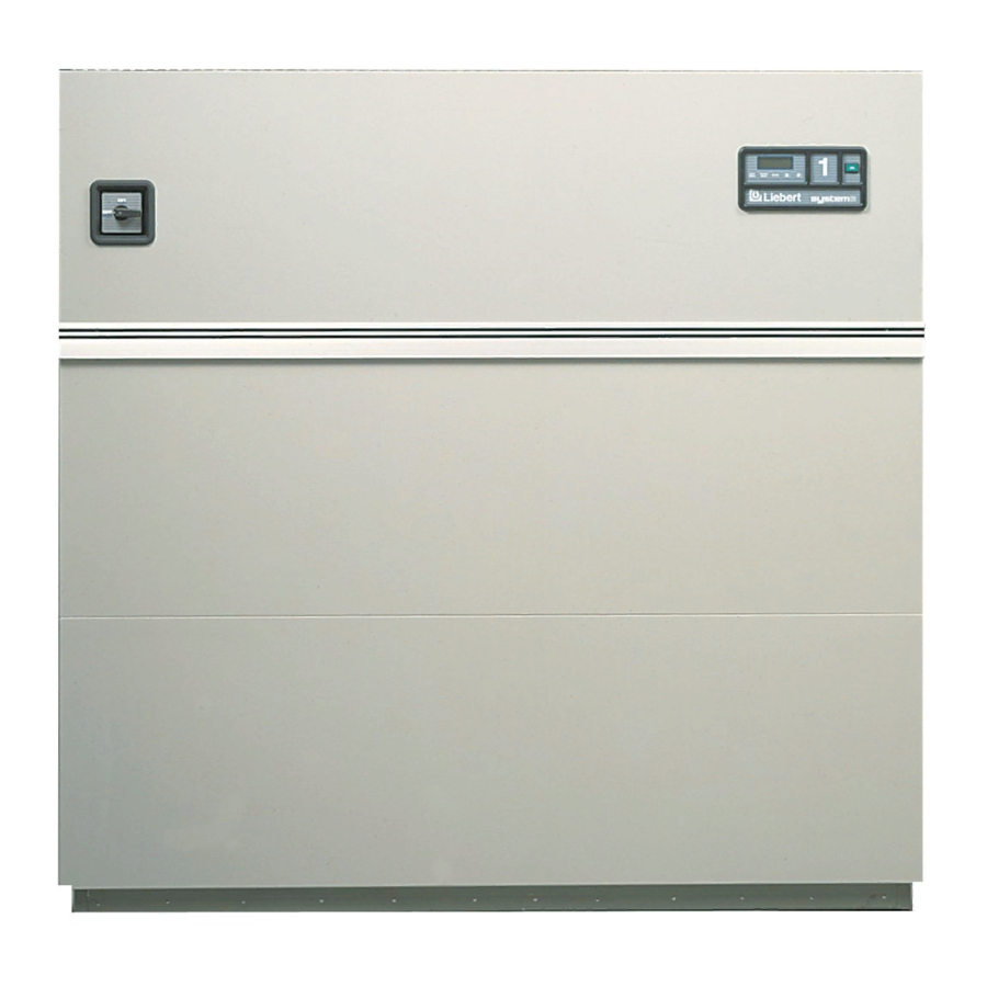
Emerson Liebert Deluxe System/3 DE Operation And Maintenance Manual (80 pages)
50 and 60 Hz, 6-30 Ton DX Systems
Brand:
Emerson
| Category:
Air Conditioner
| Size: 3.42 MB
Table of Contents
Table of Contents
3
1 Introduction
9
System Description
9
Compressorized Two-Step Systems
9
Compressorized Four-Step Systems
9
Chilled Water Systems
10
GLYCOOL ™ (Chilled Glycol Cooling) Systems
10
Dual Source Cooling Systems
10
2 Initial
11
Nitial Start Procedure
11
Additional Considerations for Upflow Units
11
3 Advanced
12
Microprocessor Controls
12
Basics
12
Display the Main Menu-AM Control
12
Figure 1 Advanced Microprocessor Control Panel
12
Figure 2 Advanced Microprocessor (AM) Control Menu
13
Main Menu (AM)-Status/Alarm Data
14
Active Alarms
14
Operating Status
14
Alarm History Log
14
Run Hours Log
14
Analog Sensors
15
Main Menu (AM)-Setpoints/Setup
15
View Setpoints Selection
15
Setup System Selection
15
Table 1 Default Control and Alarm Setpoints
15
Table 2 Setup Functions and Factory Default Values
16
Table 3 Select Options
17
DIP Switch Settings
17
Table 5 Alarm Default Time Delay
19
Run Diagnostics
21
Change Passwords
22
Main Menu (AM)-Date and Time
22
Main Menu (AM)-Status Display
23
Load Control Features
23
Short Cycle Control
23
Sequential Load Activation Control
23
Compressor Sequencing Control
23
Control Circuit Board
23
LCD Display Contrast
23
Nonvolatile Memory
24
DIP Switches
24
Control Outputs
24
Communications
24
Table 12 Control Output Leds
24
Table 6 Control Output Leds
24
Monitor Functions
25
View/Change Functions
25
4 Advanced
26
Dvanced Icroprocessor with Graphics Control Etup
26
Basics
26
Figure 3 Advanced Microprocessor with Graphics Control Panel
26
Figure 4 Advanced Microprocessor with Graphics (AG) Control Menu
27
Display the Main Menu-AG Control
28
Main Menu (AG)-Status Display
28
Main Menu (AG)-View/Set Alarms
28
Active Alarms
28
Alarm History Log
28
Setup Alarms
29
Table 7 Alarm Default Time Delay
29
Set up Custom Alarms
30
View Water Detect Floor Plan (for Optional LTM1000/LT750)
30
Setup Water Detect Floor Plan
30
Main Menu (AG)-Operating Status
31
Main Menu (AG)-View/Set Control Setpoints
31
Main Menu (AG)-Setup System
31
Table 8 Default Control and Alarm Setpoints
31
Setup Operation
32
Table 9 Setup Functions and Factory Default Values
32
Calibrate Sensors
33
Calibrate Valve Actuator
33
Select Control Algorithm
33
Select Options
33
Table 10 Select Options
33
Change Passwords
34
Select Humidity Sensing Mode
34
Set Status Display
34
Main Menu (AG)-Run Diagnostics
34
Show Inputs
35
Test Outputs
35
Test Control Board
35
DIP Switches
36
Main Menu (AG)-Date and Time
36
Main Menu (AG)-Plot Graphs
36
Table 11 DIP Switch Settings
36
Modify Plot Scales
37
Main Menu (AG)-Analog/Digital Inputs
37
Read Analog Inputs
37
Setup Analog Inputs
37
Read Digital Inputs
38
Set up Digital Inputs
38
Main Menu (AG)-View Run Hours Log
38
View 24 Hour Run Time History
38
View Total Run Hours
38
Load Control Features
38
Short Cycle Control
38
Sequential Load Activation Control
38
Compressor Sequencing Control
39
Control Circuit Board
39
LCD Display Contrast
39
Nonvolatile Memory
39
DIP Switches
39
Control Outputs
40
Communications
40
Monitor Functions
40
View/Change Functions
40
5 Response by
41
Esponse by Ontrol Ype Dvanced Icroprocessor Ontrols
41
Temperature Control
41
Cooling/Heating Required, in Percent (%)
41
Response to Control Types
41
Cooling Operation
42
Heating Operation
42
Humidity Control
43
Dehumidification/Humidification Required, in Percent (%)
43
Control Types
43
Dehumidification Operation
43
Humidification Operation
44
Control Types
44
Load Control Features
47
Short Cycle Control
47
Sequential Load Activation Control
47
Compressor Sequencing Control
47
Analog Sensors
48
Connecting the Analog Sensors
48
Figure 5 Analog Input Jumpers
48
Table 13 Changing Factory-Set Sensor Inputs
48
Table 14 Additional Connections Available after Unit Delivery
48
Water Detection Display
49
Figure 6 Connecting the LT750
49
Communications
50
Monitor Functions
50
View/Change Functions
51
6 Alarm
52
Larm Escriptions and Olutions
52
Standard Alarms
52
Change Filter
52
Compressor Overload
52
Custom Alarms (Only with Advanced Controls)
53
High Head Pressure
53
High Humidity
53
High Humidity and Low Humidity (Simultaneously)
53
High Temperature
53
High Temperature and Low Temperature (Simultaneously)
53
Humidifier Problem
53
Loss of Air Flow
54
Loss of Power
54
Low Humidity
54
Low Suction Pressure
54
Low Temperature
54
Main Fan Overload
54
Short Cycle
54
Optional/Custom Alarms
55
Loss of Water Flow
55
Smoke Detected
55
Standby GC Pump on
55
Standby Unit on
55
Water under Floor
55
7 Component
56
Omponent Peration and Aintenance Hecks and Djustments
56
C Omponent O Peration and M Aintenance , C Hecks and a Djustments
56
System Testing
56
Environmental Control Functions
56
Electric Panel
57
Filters
58
Blower Package
58
Fan Impellers and Bearings
58
Belts
58
Electronic Variable Speed Drive (Inverter)
59
Refrigeration System
59
Compressor Oil Level
59
Suction Pressure
60
Discharge Pressure
60
Suction Superheat
60
Thermostatic Expansion Valve
60
Table 15 Suction Pressures
60
Table 16 Discharge Pressures
60
Hot Gas Bypass Valve
61
Figure 7 Hot Gas Bypass
61
Air Cooled Condenser
62
Figure 8 Outdoor Fan/Condenser Configuration
62
Water/Glycol Cooled Condensers
63
Compressor Replacement
64
Humidifier
65
Infrared Humidifier
65
Figure 9 Infrared Humidifier Lamps
66
Changing Humidifier Lamps
66
Steam Generating Humidifier
67
Figure 10 Steam Generating Humidifier
67
Figure 11 Run/Drain Switch
68
Table 17 Humidifier Canister Part Numbers
69
Table 18 Faults-Canister Generator Humidifier
69
Table 19 Steam Generating Humidifier Capacity
70
Electric Reheat
71
Table 20 DIP Switch Settings for Steam Generating Humidifier
71
Figure 12 Steam Generating Humidifier Control Board
71
Table 21 Table
71
8 Troubleshooting
72
Table 23 Table
72
Table 21 Blower Troubleshooting
72
Table 22 Chilled Water Troubleshooting
72
Table 25 Table
72
Table 23 Compressor and Refrigeration System Troubleshooting
73
Table 27 Table
73
Table 24 Dehumidification Troubleshooting
75
Table 25 Glycol Pumps Troubleshooting
75
Table 26 Humidifier—Steam Generator Troubleshooting
76
Table 27 Humidifier—Infrared Troubleshooting
77
Table 28 Reheat Troubleshooting
77
9 Maintenance Inspection Checklist-Monthly
78
10 Maintenance Inspection Checklist-Semiannual
79
Advertisement
Advertisement
Related Products
Emerson DataMate 3000 Series
Emerson DME07
Emerson DME12
Emerson DMC07
Emerson DMC12
Emerson Delwarva Power Web-Programmable Thermostat
Emerson delmarva power
Emerson Delwarva Power
Emerson Sylvania DVC850C
Emerson DX-316
Emerson Categories
Controller
Control Unit
Transmitter
Measuring Instruments
Fan
More Emerson Manuals
Login
Sign In
OR
Sign in with Facebook
Sign in with Google
Upload manual
Upload from disk
Upload from URL