Sign In
Upload
Manuals
Brands
Emerson Manuals
Measuring Instruments
Hydrastep 2468CB
Emerson Hydrastep 2468CB Manuals
Manuals and User Guides for Emerson Hydrastep 2468CB. We have
1
Emerson Hydrastep 2468CB manual available for free PDF download: Operating Manual
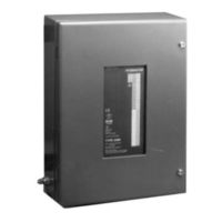
Emerson Hydrastep 2468CB Operating Manual (186 pages)
Electronic Gauging System (Dual Power Supply Version)
Brand:
Emerson
| Category:
Measuring Instruments
| Size: 2.78 MB
Table of Contents
1 Introduction to the Hydrastep 2468 Electronic Gauging System
13
Table of Contents
13
Figure 1.1 - Front Panel of the Hydrastep 2468 Gauging System, with Local Display
14
Introduction to the Hydrastep
14
Water Level Measurement
15
Figure 1.2 - Schematic of Resistance Measuring Cell and Electrodes
15
Figure 1.3 - Typical Hydrastep 2468 System Installation
16
Hydrastep 2468 Electronic Gauging System
17
Input Boards
17
Display Boards
17
System Faults (2468Cb or 2468Cd)
18
System Options
18
Output Boards
18
Remote Display Units
18
Option Details
18
Hydrastep 2468 Upgrade Paths and Available Options
19
Table 1.1 - Upgrade Paths and Available Options
19
2 2468Cb & 2468Cd Dual Power Supply Version
21
Electrode Cabling System
23
Introduction
23
Electronic Enclosure
23
Input Board (Pcb 24680501 and Pcb 24680516)
25
Analogue Output Drive Capability
25
Remote Display Drive Capability
25
Display Board (Pcb 24680515)
26
Link LK1
26
Links LK2, LK3, LK4 and LK5
27
Pcb Interconnections
27
Installation
28
Mechanical Installation
28
Electrical Installation
30
Electrode Connections
30
Connecting Cables to Water Column Electrodes
31
Connecting the Electrode Cable Assemblies to 2468 Enclosure
32
Hydrastep Power Supply Cables
33
Analogue Output Connection
35
Opto-Isolated Fault Output Connection
36
System Configuration
37
Input Board (Pcb 24680501 or 24680516)
37
Analogue Output Configuration
37
Pulsed Output Setting
38
Electrode Error Configuration
38
Configuring the Unit to Detect Electrode Error
39
Display Board 24680515
40
Link LK1 Setting
40
Configuring the 'Number of Electrodes' Switch
40
Switching Threshold' Setting
42
2.5.2.4 'Compatibility' Setting
42
Fault Analysis & Corrective Action
43
Component Replacement
50
Removing the Input Board (24680501 or 24680516)
50
Refitting the Input Board
50
Removing the Display Board 24680515
50
Refitting the Display Board
50
Parts List - Hydrastep 2468 Cb & CD Versions
51
Specification
52
2468 - Relay Output Board Option
69
3A.2 Installation
71
2.1 Storage & Pre-Installation Inspection
71
3A.2.1.1 Storage Area
71
3A.2.1.2 Pre-Installation Inspection
71
Mechanical Installation
71
3A.2.2.1 Fitting the Nylon Spacers to the Relay Output Board
72
3A.2.2.2 Mounting the Relay Output Board on to the Input Board
72
3A.1 General Description
71
2.3 Electrical Installation
73
3A.2.3.1 PCB Interconnections
73
3A.2.3.2 Relay Output Connections
73
3A.3 Relay Board Configuration
74
3.1 Relay Output Board
75
3A.3.1.1 Configuring the Relay Output Board
75
3A.3.1.3 Relay Energisation ('In Steam' or 'In Water') - SW5
76
3A.3.1.4 Electrode/Alarm Operation (RL1 Function Only) - SW6
76
3A.3.1.5 System Fault Output
76
3.2 Alarm and Tripping Facilities
77
3A.3.2.1 Philosophy
77
3A.3.2.2 Relay Interconnections for Alarm/Tripping Systems
77
3A.3.2.3 'One out of Two' Relay Alarm System
78
3A.3.2.4 'Two out of Two' Relay Alarm System
79
3A.3.2.5 'Two out of Four' Relay Alarm System
80
3A.3.2.6 'Two out of Three' Relay Alarm System
82
3A.4 Component Replacement
83
Replacement of Nylon Spacers
83
Parts List - Relay Output Board 24680504
83
3A.5 Specification
84
Delay Relay Output Board Option
85
3B.2 Installation
87
2.1 Storage & Pre-Installation Inspection
87
3B.2.1.1 Storage Area
87
3B.2.1.2 Pre-Installation Inspection
87
3B.1 General Description
87
2.2 Mechanical Installation
88
3B.2.2.1 Fitting the Nylon Spacers to the Delay Relay Output Board
88
3B.2.2.2 Mounting the Delay Relay Output Board on to the Input Board
88
2.3 Electrical Installation
89
3B.2.3.1 PCB Interconnections
89
3B.2.3.2 Relay Output Connections
89
3B.3 Delay Relay Board Configuration
90
3.1 Delay Relay Output Board
91
3B.3.1.1 Configuring the Delay Relay Output Board
91
3B.3.1.2 Electrode/Relay Selection (Relays RL1, RL2, RL3 & RL4) - SW1 to SW4
91
3B.3.1.3 Relay Energisation ('In Steam' or 'In Water') - SW5
92
3B.3.1.4 Electrode/Alarm Operation (RL1 Function Only) - SW6
92
3B.3.1.5 System Fault Output
92
3B.3.1.6 Delay Circuit Configuration
93
3B.3.1.7 Configuring the Delay Circuit Split Pads
94
3.2 Alarm and Tripping Facilities
95
3B.3.2.1 Philosophy
95
3B.3.2.2 Relay Interconnections for Alarm/Tripping Systems
95
3B.3.2.3 'One out of Two' Relay Alarm System
96
3B.3.2.4 'Two out of Two' Relay Alarm System
97
3B.3.2.5 'Two out of Four' Relay Alarm System
98
3B.3.2.6 'Two out of Four' Relay Alarm System (Contd.)
99
3B.3.2.7 'Two out of Three' Relay Alarm System
100
4.1 Replacement of Nylon Spacers
101
4.2 Parts List - Delay Relay Output Board 24680509
101
3B.4 Component Replacement
101
2468 Opto-Isolated Output Board Option
103
3C.1 General Description
105
2.1 Storage & Pre-Installation Inspection
105
3C.2.1.1 Storage Area
105
3C.2.1.2 Pre-Installation Inspection
105
3C.2 Installation
105
2.2 Mechanical Installation
106
3C.2.2.1 Fitting Nylon Spacers to the Opto-Isolated Output Board
106
3C.2.2.2 Mounting the Opto-Isolated Output Board on to the Input Board
106
2.3 Electrical Installation
107
3C.2.3.1 PCB Interconnections
107
3C.2.3.2 Opto-Isolated Output Connections
107
3C.3 Opto-Isolated Output Board Configuration
108
3.1 Configuring the Opto-Isolated Output Board
109
3C.3.1.1 Electrode/Opto-Output Selection (Opto-1, Opto-2, Opto-3 & Opto-4 Outputs) - SW1 to SW4
109
3C.3.1.2 Electrode/Alarm Operation (Output 1 Function Only) - SW6
110
3C.3.1.4 System Fault Output
110
3.2 Alarm and Tripping Facilities
111
3C.3.2.1 Philosophy
111
3C.3.2.2 Opto-Output Interconnections for Alarm/Tripping Systems
111
3C.3.2.3 'One out of Two' Opto-Output Alarm System
112
3C.3.2.4 'Two out of Two' Opto-Output Alarm System
113
3C.3.2.5 'Two out of Four' Opto-Output Alarm System
114
3C.3.2.6 'Two out of Three' Opto-Output Alarm System
115
4.1 Replacement of Nylon Spacers
116
3C.4 Component Replacement
116
4.2 Parts List - Opto-Isolated Output Board 24680505
116
3C.5 Specification
117
4 Remote Display Options 24683B, C, & D
119
Remote Display Options
121
Configuration
122
Reconfiguring the 24683B and 24683C Remote Display
122
Reconfiguring the 24683D Remote Display
123
Mechanical Installation
124
Installing the 24683B and 24683C Panel Mounted Units
124
Installing the 24683D Wall Mounted Unit
124
Electrical Installation
125
Star and Daisy Chain Connections
126
Example of a 'Star Connected' System
127
Example of a `Daisy Chain' System
128
Connecting Cables to the Remote Display
129
Connecting the Display Cables to Hydrastep 2468
130
Fault Analysis and Corrective Action
131
System Operation
131
Component Replacement
134
Specification
135
2 Installation Procedures
153
Scope of Procedures
155
Storage
155
Ambient Conditions
155
Physical Protection
155
Inspection
155
Handling Precautions
155
Installation of Water Column
155
Inspection of Mechanical Installation Work
158
3 Fault Repair and Commissioning
161
Background
163
Safety Precautions
163
Water Column Isolation
164
Electrode and Electrode Seal Leaks
164
3.1.3.1 Low Pressure Electrodes
164
3.1.3.2 High Pressure Electrodes
165
3.1.3.3 Tightening Procedure for High Pressure Electrode Installation
165
Procedure for Changing the Low Pressure Electrodes
165
And Gaskets
165
Procedure for Changing High Pressure Electrodes
166
Water Column Commissioning or Recommissioning
166
Vent and Drain Valve Repairs
166
Water Column Transient Response
167
Water Column or Pipework Blockage
167
Low Pressure Electrodes
171
High Pressure Electrodes
172
Water Column (L.p.)
173
Water Column (H.p.)
174
Water Column (H
175
Advertisement
Advertisement
Related Products
Emerson Mobrey Hydratect 2462
Emerson Hydrastep 2468 series
Emerson Hydrastep 2468CD
Emerson NGA 2000 TO2
Emerson 250-5000
Emerson 2130 RBM Consultant Pro
Emerson Rosemount 285
Emerson Rosemount 2555
Emerson Rosemount 2460
Emerson Nfinity 240V
Emerson Categories
Controller
Control Unit
Transmitter
Measuring Instruments
Fan
More Emerson Manuals
Login
Sign In
OR
Sign in with Facebook
Sign in with Google
Upload manual
Upload from disk
Upload from URL