Sign In
Upload
Manuals
Brands
Emerson Manuals
Power Supply
Branson DCX F-DP
Emerson Branson DCX F-DP Manuals
Manuals and User Guides for Emerson Branson DCX F-DP. We have
1
Emerson Branson DCX F-DP manual available for free PDF download: Instruction Manual
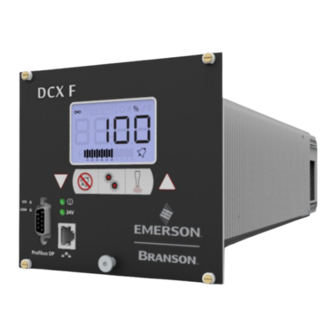
Emerson Branson DCX F-DP Instruction Manual (254 pages)
Rack Mount Power Supply
Brand:
Emerson
| Category:
Power Supply
| Size: 3 MB
Table of Contents
Copyright and Trademark Notice
2
Manual Change Information
2
Table of Contents
5
Chapter 1: Safety and Support
13
Safety Requirements and Warnings
14
Symbols Found on the Product
16
Figure 1.1 Safety-Related Labels Found on the DCX F-DP Rack Mount Power Supply
16
Figure 1.2 Safety-Related Labels Found on the DCX F-DP Rack Mount Power Supply
17
General Precautions
18
Intended Use of the System
19
Setting up the Workplace
19
Regulatory Compliance
20
How to Contact Branson
21
Table 1.2 Authorized Service Centers (South America)
21
Table 1.3 Authorized Service Centers (Asia)
22
Table 1.4 Authorized Service Centers (Europe)
24
Chapter 2: Introduction
27
Models Covered
28
Table 2.1 Models Covered in this Manual
28
Figure 2.1 the DCX F-DP Rack Mount Power Supply
29
Compatibility with Other Branson Products
30
Table 2.2 Power Supply Compatibility with Branson Converters
30
Features
31
Table 2.3 Control Features
31
The Power Supply
31
Controls and Indicators
34
Figure 2.2 DCX F-DP Rack Mount Power Supply Front Panel Controls and Indicators
34
Table 2.4 DCX F-DP Rack Mount Power Supply Front Panel Controls and Indicators
34
Table 2.5 LCD Description
34
Figure 2.3 LCD Description
36
Figure 2.4 DCX F-DP Rack Mount Power Supply Back Panel
39
Table 2.6 Connections to the DCX F-DP Rack Mount Power Supply
39
Welding Systems
40
Principle of Operation
40
Glossary
41
Table 2.7 Glossary
41
Chapter 3: Delivery and Handling
45
Shipping and Handling
46
Environmental Specifications
46
Table 3.1 Shipping Specifications
46
Receiving
47
Scope of Delivery
47
Table 3.2 Inspect the Power Supply
47
Unpacking the Power Supply
48
Table 3.3 Unpacking the Power Supply
48
Take Inventory of Small Parts
49
Table 3.4 Small Parts Included with the Power Supply Assemblies
49
Table 3.5 DCX F-DP Rack Mount Power Supply System Cables
49
Returning Equipment
50
Chapter 4: Technical Specifications
51
Technical Specifications
52
Table 4.1 Environmental Specifications
52
Electrical Specifications
52
Table 4.2 Electrical Input Operating Voltages
52
Table 4.3 Input Current and Fuse Specifications
53
Table 4.4 Continuous Duty Maximum Power
53
Physical Description
54
Table 4.5 Dimensions and Weights of DCX F-DP Rack Mount Power Supply
54
EU Declaration of Conformity
55
Figure 4.1 EU Declaration of Conformity
55
Declaration of Conformity
56
Figure 4.2 UK Declaration of Conformity
56
PROFIBUS Certificate
57
Figure 4.3 PROFIBUS Certificate
57
Figure 4.4 Association Trademark
58
Figure 4.5 Technology Trademarks
58
Figure 4.6 Certification Trademark
58
Figure 4.7 Certified by PI Trademark
58
General Terms
59
Chapter 5: Installation and Setup
61
About Installation
62
Installation Requirements
63
Figure 5.1 DCX F-DP Rack Mount Power Supply Dimensional Drawing (Small)
63
Figure 5.2 DCX F-DP Rack Mount Power Supply Dimensional Drawing (Medium)
65
Figure 5.3 DCX F-DP Rack Mount Power Supply Dimensional Drawing (Large)
66
Table 5.1 Environmental Requirements
67
Electrical Input Power Ratings
67
Table 5.2 Input Current and Circuit Breaker Specifications
67
Pneumatic Requirements
67
Installation Steps
68
Basic Installation Notes
68
Mount the Power Supply
69
Mounting Considerations
69
Figure 5.4 LCD Viewing Angle
69
Electrical Connections
70
Figure 5.5 DCX F-DP Rack Mount Power Supply Connections
70
Table 5.3 DCX F-DP Rack Mount Power Supply Connections
70
User I/O
71
User I/O Connections
71
Figure 5.6 User I/O Cable Identification and Wire Color Diagram
72
Table 5.4 User I/O Cable Identification and Wire Color Diagram
72
Table 5.5 User I/O Cable Pin Assignments
73
Table 5.6 Default Branson User I/O Connector Pin Assignments
75
Table 5.7 Digital Input Functions
77
Table 5.8 Digital Output Functions
79
Table 5.9 Analog Input Functions
81
Table 5.10 Analog Output Functions
82
Figure 5.7 Typical Digital I/O Wiring Examples
83
Figure 5.8 Typical Analog I/O Wiring Examples
83
Figure 5.9 RF Cable Connection
84
Table 5.11 RF Cable Connection
84
Table 5.12 Input Power Connection
85
Power Supply Setup
87
Table 5.13 Power Supply Features
87
Assembling the Acoustic Stack
88
Figure 5.10 Assembling the Acoustic Stack
89
Table 5.14 Acoustic Stack Description
89
Table 5.15 Stack Torque Values
90
Table 5.16 Tools
90
Table 5.17 20 Khz System
91
Table 5.18 30 Khz System
91
Table 5.19 40 Khz System
91
Figure 5.11 Connecting Tip to Horn
92
Table 5.20 Tip to Horn Torque Values
92
Converter Cooling
93
Table 5.21 Continuous Duty Max. Power & Full Power Duty Cycle
93
Table 5.22 Converter Cooling Procedure
94
Testing the Installation
95
Still Need Help
96
Converters and Boosters
98
Figure 6.1 20 Khz Typical Converter Dimensions
98
Table 6.1 20 Khz Converter
98
Figure 6.2 20 Khz Booster Dimensions
99
Table 6.2 20 Khz Booster
99
Figure 6.3 20 Khz Converter/Booster/Horn, Typical Dimensions
100
Table 6.3 20 Khz Converter/Booster/Horn
100
Figure 6.4 30 Khz Converter Dimensions
101
Table 6.4 30 Khz Converter
101
Figure 6.5 30 Khz Booster Dimensions
102
Table 6.5 30 Khz Booster
102
Figure 6.6 30 Khz Converter/Booster/Horn, Typical Dimensions
103
Table 6.6 30 Khz Converter/Booster/Horn
103
Figure 6.7 40 Khz Booster Dimensions
104
Table 6.7 40 Khz Booster
104
Figure 6.8 40 Khz Converter/Booster/Horn, Typical Dimensions
105
Table 6.8 40 Khz Converter/Booster/Horn
105
Component Functional Description
106
Chapter 7: Operation
109
Setting Primary Parameters
110
Table 7.2 Continuous Mode Operational Sequence
111
Table 7.3 Time Mode Parameters
113
Table 7.4 Time Mode Operational Sequence
114
Table 7.5 Energy Mode Parameters
115
Table 7.6 Energy Mode Operational Sequence
116
Table 7.7 Peak Power Mode Parameters
117
Table 7.8 Peak Power Mode Operational Sequence
117
Table 7.9 Ground Detect Mode Parameters
119
Table 7.10 Ground Detect Mode Operational Sequence
119
Setting Limits
121
Table 7.11 Time Window Limit High Parameters
121
Table 7.12 Time Window Limit High Operational Sequence
122
Table 7.13 Time Window Limit Low Parameters
123
Table 7.14 Time Window Limit Low Operational Sequence
124
Table 7.15 Energy Window Limit High Parameters
125
Table 7.16 Energy Window Limit High Operational Sequence
126
Table 7.17 Energy Window Limit Low Parameters
127
Table 7.18 Energy Window Limit Low Operational Sequence
128
Figure 7.1 Power Window Limits
129
Table 7.19 Power Window Limit High Parameters
130
Table 7.20 Power Window Limit High Operational Sequence
131
Table 7.21 Power Window Limit Low Parameters
132
Table 7.22 Power Window Limit Low Operational Sequence
133
Setting the Amplitude
134
Figure 7.2 LCD at Power up
134
Table 7.23 Setting the Amplitude Using the Front Panel Controls
134
Figure 7.3 LCD When in External Amplitude Control Mode
135
Resetting the Power Supply Alarms
136
Table 7.24 Resetting the DCX F-DP Rack Mount Power Supply
136
Configuring the Power Supply Registers
137
Table 7.25 Steps to Configure the Power Supply Registers
137
Table 7.26 Power Supply Registers
139
Save/Recall Presets
142
Table 7.27 Save Preset
142
Table 7.28 Recall Preset
143
LCD Bar-Graph
145
Table 7.29 Power Bar-Graph Interpretation Examples
145
Table 7.30 Frequency Bar-Graph Interpretation - 20 Khz (50 Hz Segment)
146
Table 7.31 Frequency Bar-Graph Interpretation - 30 Khz (76 Hz Segment)
146
Table 7.32 Frequency Bar-Graph Interpretation - 40 Khz (100 Hz/Segment)
147
Table 7.33 Frequency Bar-Graph Interpretation Examples
147
Ultrasonics Test Procedure
148
Table 7.34 Power Supply Ultrasonic Test Procedure (Front Panel)
148
Using the I/O Connections
150
Figure 7.4 Test Connections
150
Table 7.35 Power Supply Ultrasonic Test Procedure (User I/O)
150
Chapter 8: PROFIBUS DP Operation
151
LED Status Indicator
152
Bus Communication
153
Network Topology
153
Table 8.2 Data Bandwidth Demands on PROFIBUS Communications Systems
153
Network Connectors
154
Table 8.3 Pin-Out Listing for the PROFIBUS Bus Plug Connector
154
Table 8.4 Line Types
155
Configuration
156
Table 8.5 User Parameters
156
Table 8.6 Communication Channel (PKW)
157
Table 8.7 Subdivisions of the Communication Channel (PKW)
158
Table 8.8 Identifier (PKE) of the Communication Channel (PKW)
158
Table 8.9 Answer Code - Master > Slave
159
Table 8.10 IND (High Byte)
160
Table 8.11 Answer Code: Slave > Master
160
Table 8.12 Error Number PKE, Low Byte
161
Figure 8.2 Writing and Reading Parameters
163
Process Data Channel (PZD)
165
Table 8.13 DCX Inputs/Plc Outputs (4 Words)
165
Table 8.14 Control Word (STW1)
166
Table 8.15 HFS Bit (Control Word)
167
Table 8.16 PSN Bit (Control Word)
167
Table 8.17 Control Word (STW2)
169
Table 8.18 DCX Outputs/Plc Inputs (12 Words)
170
Table 8.19 Status Word (ZSW1)
171
Table 8.20 HFS Bit (Status Word)
172
Table 8.21 PSN Bit (Status Word)
172
Table 8.22 Status Word (ZSW2)
174
Table 8.23 Stack Function
175
Table 8.24 Process Data Channel Information for Run
175
Table 8.25 Process Data Channel Information for Seek
175
Table 8.26 Process Data Channel Information for Scan
176
Table 8.27 Process Data Channel Information for Reset
176
Chapter 9: Maintenance
177
General Maintenance Considerations
178
DCX F-DP Rack Mount Power Supply Preventive Maintenance
180
Table 9.1 Stack Reconditioning Procedure
182
Figure 9.1 Reconditioning Stack Mating Surfaces
183
Table 9.2 Reconditioning Stack Mating Surfaces
183
Table 9.3 Stack Torque Values
183
Table 9.4 Stack Reassembly for a 20 Khz System
184
Table 9.5 Stack Reassembly for a 30 Khz System
184
Table 9.6 Stack Reassembly for a 40 Khz System
185
Table 9.7 Stud Torque Values
185
Recommended Spare Stock
186
Table 9.8 DCX F-DP Rack Mount Power Supply System Cables
186
Table 9.9 Suggested Spares
187
Table 9.10 Converters Compatible with the DCX F-DP Rack Mount Power Supply
188
Table 9.11 DCX F-DP Rack Mount Power Supply Compatible Boosters
189
Table 9.12 Other Items Used with the DCX F-DP Rack Mount Power Supply
191
Troubleshooting
192
Table 9.13 Troubleshooting
192
Table 9.14 Troubleshooting Common Electrical Problems
193
Table 9.15 Troubleshooting Ultrasonic Power Problems
194
Table 9.16 Troubleshooting Weld Cycle Problems
195
Cold Start Procedure
196
Performing a Cold Start
196
Table 9.17 Steps to Perform a Cold Start
196
Appendix A: Communication Channel Alarms
197
Overload Alarms (Group 0)
198
Table A.1 Overload Alarms (Group 0)
198
Cutoff Alarms (Group 1)
200
Table A.2 Cutoff Alarms (Group 1)
200
Setup Alarms (Group 2)
201
Table A.3 Setup Alarms (Group 2)
201
Cycle Modified Alarms (Group 3)
202
Table A.4 Cycle Modified Alarms (Group 3)
202
Warning Alarms (Group 4)
203
Figure C.1 Weld Cycle
203
Table A.5 Warning Alarms (Group 4)
203
Limit Alarms (Group 5)
204
Table A.6 Limit Alarms (Group 5)
204
Equipment Failure Alarms (Group 6)
205
Table A.7 Equipment Failure Alarms (Group 6)
205
No Cycle Alarms (Group 7)
207
Table A.8 no Cycle Alarms (Group 7)
207
Communication Failure Alarms (Group 8)
208
Table A.9 Communication Failure Alarms (Group 8)
208
Hardware Alarms (Group A)
209
Table A.10 Hardware Alarms (Group A)
209
Non-Cycle Overload Alarms (Group B)
210
Table A.11 Non-Cycle Overload Alarms (Group B)
210
Appendix B: Communication Channel Commands
213
Weld Parameters
214
Table B.1 Weld Parameters
215
Seek Stack Parameters
216
Table B.2 Seek Stack Parameters
216
Test Stack Parameters
217
Table B.3 Test Stack Parameters
217
Scan Stack Parameters
218
Table B.4 Scan Stack Parameters
218
Common Stack Parameters
219
Table B.5 Common Stack Parameters
219
Alarm Commands
220
Table B.6 Alarm Commands
220
Weld Parameter Status
221
Table B.7 Weld Parameter Status
221
Weld Status Commands
222
Table B.8 Weld Status Commands
222
Seek Parameter Status
223
Table B.9 Seek Parameter Status
223
Seek Stack Commands
224
Table B.10 Seek Stack Commands
224
Test Parameter Status
225
Table B.11 Test Parameter Status
225
Test Stack Commands
226
Table B.12 Test Stack Commands
226
Scan Parameter Status
227
Table B.13 Scan Parameter Status
227
Scan Stack Commands
228
Table B.14 Scan Stack Commands
228
Process Data Channels
229
Table B.15 Process Data Channels
229
Token Access
230
Table B.16 Token Access
230
Version, System, & RTC Information
231
Table B.17 Version, System, & RTC Information
231
System Configuration Parameters
232
Table B.18 System Configuration Parameters
232
Timing Diagrams
234
Weld Cycle
234
Figure C.2 Weld Cycle with Overload Alarm and External Reset
235
Figure C.3 Weld Cycle with Cutoff Alarms and External Reset
236
Figure C.4 Weld Cycle Using Presets
237
Figure C.5 RF Switching Direct with Feedback with and Without Alarm
238
Figure C.6 RF Switching I/O Direct with Feedback with and Without Alarm
238
Figure C.7 RF Switching I/O Direct with Feedback with and Without Alarm and Load on Start
239
Figure C.8 RF Switching I/O with off with and Without Alarm and Load on Start
239
Figure C.9 RF Switching I/O with off with Feedback with and Without Alarm
240
Figure C.10 RF Switching with off with Feedback with and Without Alarm
240
Figure C.11 Timing Diagram for All Other Modes with Actuator
241
Figure C.12 Timing Diagram for Cycle Abort with Actuator
242
Figure C.13 Timing Diagram for Ground Detect with Actuator
243
Manual's Revisions
246
Appendix D: Manual's Revisions
246
Figure D.1 Manufacturing Date on the Information Label
246
Figure D.2 Location of the Information Label on the Back of the DCX F-DP Rack Mount Power Supply
247
Advertisement
Advertisement
Related Products
Emerson Branson LPX
Emerson Branson DCX RM S
Emerson Bristol ControlWave ExpressPAC
Emerson Branson 2000 Series
Emerson BRANSON Ultraseal 20 Series
Emerson Bristol ControlWave Express
Emerson Bristol ControlWave LP
Emerson Bristol ControlWave PAC
Emerson Bristol ControlWave EFM
Emerson Bettis BHH 1000
Emerson Categories
Controller
Control Unit
Transmitter
Measuring Instruments
Fan
More Emerson Manuals
Login
Sign In
OR
Sign in with Facebook
Sign in with Google
Upload manual
Upload from disk
Upload from URL