Sign In
Upload
Manuals
Brands
eltech Manuals
Security System
GsmAlarm-500E
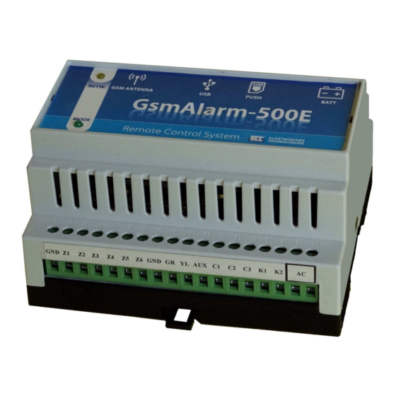
eltech GsmAlarm-500E Manuals
Manuals and User Guides for eltech GsmAlarm-500E. We have
1
eltech GsmAlarm-500E manual available for free PDF download: Instruction Manual
eltech GsmAlarm-500E Instruction Manual (62 pages)
GSM Alarm and Remote Control System
Brand:
eltech
| Category:
Security System
| Size: 1 MB
Table of Contents
Table of Contents
2
General Information
5
Safety Instructions
5
Package Content
6
Introduction
7
Connectors and LED Indicators
8
Zone Input Terminals Z1 to Z6
8
Keypad Connection Terminals GR and YL
8
Auxiliary Power Terminal aux
9
Programmable Output Terminals C1, C2 and C3
9
BELL/SIREN Connection Terminals K1, K2
9
AC Power Terminals
9
BAT Connector
9
External Microphone Connector
9
RESET Button
9
LED Indicators
10
NETWORK: GSM Module State and Signal Strength Indicator
10
MODE: Alarm System Status Indicator
10
Installation
11
General Installation Instructions
11
Wiring Diagrams
13
System with Keypad Access Control
13
System with Ibutton Access Control
13
Wiring Diagram When the Device Operates in the Gate Control Mode
14
Ways to Connect Alarm Zones
15
Connection of Temperature Sensors
16
Programming
17
General Programming Instructions
17
User and Alarm Monitoring Station Numbers
17
Programming with Standard Mobile Phone
18
Programming with SMS
18
Programming System Parameters with SMS
20
Programming Zones
20
Parameter "A": Input Triggering Conditions
22
Parameter "M": System State after Input Triggering
23
STAY and SLEEP. Tamper Recognition
24
E", "F", "G", "H", "J", "K", "L", "P", "T
24
Output C1-C4 (K1, K2) Operating Mode
26
Outputs C1-C4 (K1, K2): Inverted Mode and Operating Time Units
27
Configuration of the Gate Control Mode
27
Parameter "E": the Way User Is Informed about Arming/Disarming
28
Parameter "F": System Response to Incoming Calls and Number of Calls in Alarm State
28
Parameter "G": SMS Delay Time in Case of Power Supply Failure
28
Parameter "L": SMS Structure and SMS Password Functionality
29
Hours Tamper Supervision
29
Programming Partition Names
29
Setting System Clock
30
Programming 24 Hour Timer
30
Timer Instructions
31
Programming the Description of Input Zone State
32
Programming User Names
32
Programming SMS Password
32
Programming the System Using the Keypad
33
Programming Access Codes
34
User Access Code Functionality
35
Exit Delay Time
35
Parameter "T": Entry Delay Time or Triggering Temperature
36
Parameter "A": Input Triggering Conditions
36
Parameter "M": System State after Input Triggering
36
Tamper Recognition (Parameter P)
37
Parameter "I": Pulse Counting Mode or Temperature Hysteresis
37
Zone Response Time
38
Operating Time of Outputs C1-C4 and BELL
38
Operating Mode of Outputs C1-C4 and BELL
38
Outputs C1-C4 (K1, K2): Inverted Mode and Operating Time Units
39
Parameter "E": the Way User Is Informed about Arming/Disarming
39
Parameter "F": System Response to Incoming Calls and Number
39
Of Calls in Alarm State
39
Parameter "G": Delay Time of Report SMS about the Power Supply Failure
40
Parameter "H": Data Transfer to the Alarm Monitoring Station
40
Parameter "J": System Response to Intentional GSM Jamming
40
Parameter "L": SMS Structure and SMS Password Functionality
40
Parameter "P": Partitioning
40
Access Code Length (4 or 6 Digits)
41
Exit Delay Audible Indication
41
Assigning Keypad Zones
41
Setting System Clock
41
Programming 24 Hour Timer
42
Programming CONTACT ID User Account Number
42
Temperature Correction
43
The Way User Is Informed about STAY or SLEEP Mode Activation
43
The Way User Is Informed about STAY or SLEEP Mode Deactivation
43
Keypad Indicator Stayd
43
Programming Ibutton Keys
43
Programming and Diagnostics over the Internet
44
Resetting System Settings to Factory Defaults
46
Manufacturer Programmed Parameters
46
Data Transfer to Alarm Monitoring Station
47
GPRS Channel Settings
47
Audio Channel Settings
48
Programming CONTACT ID User Account Number
48
Modes of Data Transfer to the Central Monitoring Station
48
CONTACT ID Protocol Codes
49
System Control Using the Keypad
50
Keypad Keys and LED Indicator Functionality
50
Key - Extended Indication Mode
50
TBL] Key - Trouble Display
50
MEM] Key - Alarm Memory Display
51
BYP] Key - Bypass Programming
51
CLEAR] Key
51
ENTER] Key
51
Indicator
51
Stayd" (Status) Indicator
51
OFF" Indicator
51
ARM", "SLEEP" and "STAY" Indicators
52
Regular Arming
52
Stay & Sleep Arming
52
Disarming & Deactivating an Alarm
53
Panic Alarms
53
Control of Separate Partitions
53
Programmable Outputs Control
53
System Control Using Ibutton Access Keys
53
Remote Arming & Disarming
54
System Operation in Alarm State
55
Power Supply Monitoring
55
GSM Jamming Detection
56
System Control Using DTMF and SMS Commands
57
Smartcloud Server
60
Settings and Activation
60
Warranty
61
Technical Characteristics
62
Advertisement
Advertisement
Related Products
eltech GsmAlarm-600
eltech GsmAlarm-500
eltech Categories
Security System
More eltech Manuals
Login
Sign In
OR
Sign in with Facebook
Sign in with Google
Upload manual
Upload from disk
Upload from URL