Sign In
Upload
Manuals
Brands
Elgas Manuals
Data Loggers
DATCOM
User Manuals: Elgas DATCOM Battery Powered Datalogger
Manuals and User Guides for Elgas DATCOM Battery Powered Datalogger. We have
1
Elgas DATCOM Battery Powered Datalogger manual available for free PDF download: Operating Instructions Manual
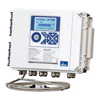
Elgas DATCOM Operating Instructions Manual (228 pages)
GAS VOLUME CORRECTOR, ELECTRONIC DATALOGGER
Brand:
Elgas
| Category:
Data Loggers
| Size: 8 MB
Table of Contents
Table of Contents
3
Contents
3
Symbols and Terms
9
Introduction
11
Basic Description of the Device
11
Securing the Device
13
Versions of the Device
14
Elcor, Datcom
14
Elcorplus, Datcomplus
15
Elcorplus Indexer
16
Safety
17
General
18
Using the Device in Potentially Explosive Atmospheres
18
Special Conditions for Use
21
Risks of Use
21
Connecting External Devices
21
Technical Parameters
22
Mechanical Parameters
22
Environment
22
Corrector Power Supply
23
Safety, Explosion Protection
23
Device Accuracy
24
Measurement Parameters
24
General
24
Pressure Measurement
25
Temperature Measurement
27
Digital Inputs
27
Digital Outputs
29
Communication Inputs/Outputs
30
Quantities Archiving
30
Optional Extension
31
Interface Modules for Connecting the Gas Meter Encoders
31
Communication Modules
32
Modules for Connecting External Power Supply
34
Analogue Inputs/Outputs Modules
35
Other Modules
36
Explosion Safety Parameters
39
Installation and Commissioning
44
Dimensions of the Device
44
ELCOR Corrector
44
Fig. 1 ELCOR Device Dimensions
44
Fig. 2 Elcorplus Device Dimensions
45
Elcorplus Corrector
45
Fig. 3 Elcorplus Indexer Device Dimensions
46
Elcorplus Indexer Corrector
46
Security Marks of the Device
46
Fig. 4 Internal Security Marks of ELCOR
47
Fig. 5 Internal Security Marks of Elcorplus
48
Fig. 6 External Security Marks of the Device
48
Data Plates
49
Fig. 7 Examples of Data Plates
50
Mechanical Installation
51
Fig. 8 Mounting the Brackets on the Device
52
Mounting the Device on the Plate
52
Table 1 Mounting Plates Supplied
53
Fig. 9 Mounting of the ELCOR Convertor on the Mounting Plate
53
Mounting the Device on a Pipe
54
Fig. 10 Mounting Dual Channel Elcorplus on a Mounting Plate
54
Fig. 11 Mounting the Device on a Pipe (Elcorplus)
55
Installation of Elcorplus Indexer on Gas Meter
56
Fig. 12 Installation of ELCOR on Piping Using a Special Holder
56
Fig. 13 Installation of ELCOR on ELGAS Radial Turbine Gas Meter
56
Fig. 14 Installation of Elcorplus Indexer Device on the Gas Meter
57
Fig. 15 Indexer Rotation Direction Adjustment (Elcorplus Indexer)
58
Connecting the Pressure Transducer
58
Connecting the Temperature Transducer
58
Fig. 16 Mounting the Temperature Sensor on the Pipe
59
Fig. 17 Mounting the Temperature Sensor Using a Straight Weld-On Fitting
59
Table 2 Weld-On Fittings and Thermowells Appropriate for the Pipe Diameters
59
Electric Installation
60
Basic Installation Requirements in Terms of Interference and EMC
60
EMC Connection Principles
60
Fig. 18 Interconnection Pipelines
62
Fig. 19 Installation of a Converter with Pressure and Temperature Transducer, External Power Supply and Remote Communication with an Emphasis on EMC
65
Fig. 20 Connecting the Cable Shields in the Cable Glands
66
Connecting Cables
66
Electrical Connection
66
Fig. 21 Cable Glands Arrangement
68
Table 3 Cable Entries - Recommended Use
68
Connecting Gas Meters
69
Table 4 Cables Recommended to Connect the Gas Meter
70
Fig. 22 Connecting LF Gas Meter to ELCOR
71
Fig. 23 Connecting LF Gas Meter to Elcorplus (Single Channel)
71
Fig. 24 Connecting LF Gas Meter with the Detection of Rotation Direction to ELCOR
72
Fig. 25 Connecting LF Gas Meter with the Detection of Rotation Direction to Elcorplus
72
Fig. 26 Connecting LF Gas Meters to Elcorplus (Dual Channel)
73
Fig. 27 Connecting LF Gas Meters to Elcorplus
73
Fig. 28 Connecting HF Gas Meters to Elcorplus (Dual Channel)
74
Fig. 29 Connecting Gas Meter with NAMUR Encoder to Elcorplus
74
Connecting Binary Inputs
75
Fig. 30 Connecting Gas Meter with SCR Encoder to Elcorplus
75
Table 5 Cables Recommended to Connect Binary Inputs
75
Connecting Binary Outputs
76
Fig. 31 Connecting Digital Outputs Via B-DO Separation Barrier (ELCOR)
76
Table 6 Cables Recommended to Connect Binary Outputs to the B-DO Module
76
Table 7 EDT 96 and EDT 101 Transducers Wire Colors
77
Fig. 32 Connecting Digital Outputs Via B-DO Separation Barrier (Elcorplus)
77
Connection of Pressure and Temperature Transducers
77
Connecting External Power Supply
78
Fig. 33 EDT 96 and EDT 101 Transducers Connection
78
Fig. 34 Connecting the External Power Supply of the Corrector
79
Table 8 Cables Recommended for External Power Supply for the Corrector and the Modem
79
Fig. 35 PS-M External Power Supply for the Internal Modem from PS-M Source
80
Connection of RS232/RS485 Communication
81
Fig. 36 External Power Supply to the Corrector and the Internal Modem
81
Table 9 Assigning the Terminals of the Terminal Block SLOT 1 and SLOT 2 When S1-COM Module
81
Table 10 Recommended Cables for RS232 and RS485 of the Corrector
82
Fig. 37 Communication Via RS232/RS485 Using B-RS Module
83
Fig. 38 Connecting B-RS When External Modem Is Connected
84
Fig. 39 Elcorplus, Communication Via Two Independent Interfaces RS232/RS485
84
Commissioning
85
Fig. 40 Communication Using the Barrier MTL 5051
85
Connecting the Battery
86
Connecting the Modem Battery
87
Fig. 41 Connecting the Device Battery
87
Fig. 42 Elcorplus Indexer with Alkaline Battery B-03A Located above Slot 0
87
Fig. 43 Connecting the Modem Battery for ELCOR
88
Fig. 44 Connecting the Modem Battery for Elcorplus
88
Installing SIM Card in the Modem
89
Operating the Device
90
Keypad
91
System Menu
91
Fig. 45 Function of the Keys
91
Fig. 46 Basic Navigation from the Home Screen
93
Table 11 Status Icons of the Display
93
Main Menu
94
Fig. 47 Main Menu of the Device and the First-Level Submenu
94
Fig. 49 Navigation in the Archives (in this Case, with Archiving Frequency 1 H)
95
Archives Menu
95
Fig. 48 Example of Actual Values Display
95
Actual Values Menu
95
Fig. 50 Display of the Settings Archive
96
Fig. 51 Display of the Status Archive
96
Device Parameters Menu
97
Fig. 52 Example of the Displayed Information on Device Components
98
Device Configuration Menu
99
System Data Menu
100
About Device
100
Device Reset
100
Communication
101
Table 12 RSSI Signal Strength Conversion Table between Dbm, %, and Relative Units
102
Table 13 Error Codes of the Modem
103
Frozen Values
104
Diagnostics
105
Current Status
105
Summary Status
105
Summary Status Reset
105
Fig. 53 Example of a Summary Status Display
105
Device Test
106
Device Errors Display
106
Table 14 List of Events - Error Messages (Err Indication)
107
Status Word of the Device
108
Table 15 List of Events - Error Messages (Wrnr Indication)
108
Technical Description of the Device
110
Architecture of the Device
110
Main Parts of the Device
111
Fig. 54 Main Parts of the ELCOR Device
111
Fig. 55 Main Parts of the Elcorplus Device
112
Elcorplus Indexer - Description of Mechanical Indexer
113
Table 16 Connection of Mechanical Indexer to SLOT 0 Terminals
113
Fig. 56 Mechanical Indexer - Settings of TAMPER Parameters in the Corrector Via Compass Software (Signal of an Attempt to Disturb the Function of the Indexer by an External Magnetic Field)
114
Fig. 57 Functional Diagram of ELCOR
115
Fig. 58 Functional Diagram of Elcorplus
116
Modules, Principles of Use
117
Fig. 59 Arrangement of Elcorplus Slots
117
Marking of Modules
118
Fig. 60 Plug-In, Identification Labels
118
Table 17 Labeling of Internal Modules
119
Installing the Modules
120
Installing the External Power Supply of the Modem
120
Replacement of the Internal Modem
121
Fig. 61 Modem Replacement
122
Power Supply of the Device
123
Batteries to Power the Device
124
Replacing the Battery
127
Battery to Power the Modem
129
Fig. 62 Main Battery
129
Replacing the Modem Battery
130
Back-Up Battery
130
External Power Supply
130
Digital Outputs, Modified Use
131
Table 18 External Power Supply, Components Required
131
Fig. 63 Placing JP1 Jumper on I/O Board
132
Table 19 Operating Parameters of DO1 and DO2 Outputs Depending on Shorting Jumper JP1
132
Internal Modem, Using External Antenna
133
Using the Device with an External Antenna
133
Modifying the Device for Connecting an External Antenna to the Modem
133
Software
134
Fig. 64 External Antenna Cable Adapter
134
Downloading Application Firmware Using "Remote Download" Method
135
Storing Data in the Device
135
Principle of the Function
135
Conversion Using State Equation
135
Substitute Volume Values
136
Volume Correction under the Measurement Conditions
136
Conversion of Volume to Energy
137
Fig. 65 Volume and Energy Calculations - Calculation Scheme
139
Metrological Features
140
Temperature Measurement
140
Pressure Measurement
140
Compressibility Calculation
140
PTZ, TZ Conversion
140
Fig. 66 Transducer Dimensions
140
Table 20 Limitation of Standard Applicability Given by Limitation in Compressibility Calculation (AGA, SGERG)
141
Table 21 Limitation of Ranges Applicability Given by Limitation in Compressibility Calculation (GOST)
142
T Conversion
142
Fig. 67 Setting the Substitute Compressibility Value K for Calculating C (SW Compass)
142
Volumes Measurement and Calculation
143
Calculation of Conversion Number C for Volume Conversion
143
Fig. 68 Setting the Constant Compressibility Value for Calculating C (SW Compass)
143
Fig. 69 Setting the Replacement Pressure Value (Compass SW)
144
Fig. 70 Constant Pressure Value Setting (SW Compass)
145
Activities at Error Conditions Occurrence
146
Fig. 71 Setting the Replacement Temperature Value (SW Compass)
146
Fig. 72 Setting a Constant Temperature Value (SW Compass)
146
Respecting the Change of the Gas Flow Direction in the Gas Meter
148
Fig. 73 Storing Volumes in the Counters in Error-Free and Error-Free Condition
148
Fig. 74 Processing the Volumes at the Gas Meter Revers Rotation
149
Connecting Inputs
150
Table 22 Options of Digital Inputs for the ELCOR Device
150
Table 23 Options of Digital Inputs for the Elcorplus Device
150
Fig. 75 EXT1-T Add-On Terminal Board for S0-EXT1 Module
151
Table 24 Options of Analogue Inputs for the Elcorplus Device
151
Table 25 Options of Digital Inputs for the Elcorplus Indexer Device
151
Table 26 Options of Analogue Inputs for the Elcorplus Indexer Device
152
Connecting a Gas Meter with an Encoder
152
HF Pulse Inputs (NAMUR)
152
Binary Inputs
152
LF Pulse Inputs
152
Device Specifics When Using the Encoders
153
Gas Meter Installing and Replacing
153
Table 27 Encoders - Limitation of Reading Period
153
Communication with the Device
154
Table 28 Communication Options of the Devices (Max. Possibilities)
154
62056-21 (IEC-1107) Optical Interface
156
Modules of the Internal Modems
156
Table 29 Setting Range of Device Communication Addresses
156
Connecting Communication Devices Via RS232 Interface
157
Connecting an External Modem
158
Fig. 76 Principle of Connection with PC and External Modem Via Module B-RS
158
Encrypting Data When Communicating with the Master System
158
Function Description
160
Quantities Designation
160
Actual Values
160
Archives
161
Data Archive
162
Table 30 Quantities Archiving Options
162
Daily Archive
162
Monthly Archive
162
Binary Archive
163
Limit Archive
163
Status Archive
163
Settings Archive
163
Billing Archive
163
Gas Composition Archive
163
Device Parametrization
163
SW Parameterization Using the Service SW
163
Tariff Counters
164
Protection against Change of Metrological Parameters
164
Other Features of the Device
164
Summer/Winter Time (DST)
164
Time Synchronization
164
Protection Switches
165
Passwords
165
Table 31 Service Switch Settings
165
Table 32 Password Format
166
Levels of Access
168
Table 33: Password Groups and Their Specification
168
Table 34 User Access Level - for the "Full" Function of the Service Switch
170
Table 35 ASC Access Level
170
Plug-In Modules for Elcorplus Corrector
171
Accessories
171
Plug-In Modules for ELCOR Corrector
171
External Modules
172
Intrinsically Safe Sources for External Power Supply (Elcorplus Only)
172
Separation and Communication Modules
172
Fig. 77 Elcorplus, Example of Use of External Modules
173
Fig. 78 Elcorplus, Example of Use of External Modules
174
Fig. 79 ELCOR, Example of Use of External Modules
175
Fig. 80 ELCOR, Example of Use of External Modules
175
Other Accessories
176
Appendix 1: Device Variant with the Segment Display
177
Device Operation
177
Standard Display
177
Display Using Keypad Keys
177
Display of the Device
178
System Menu
179
Main Menu
179
Table 36 Meaning of the Display Icons
179
SYSTEM Menu - System Data
185
CONFIG Menu
185
PARAM Menu
185
USER 1, USER 2 Menu
185
ACTUAL Menu - Actual Values Display
185
DIAG Menu Item - the Device Diagnostics
186
Appendix 2: Elcorplus Version for Zone 2
187
Introduction
187
Safety
188
General
188
Use in Potentially Explosive Atmospheres Zones
188
Special Conditions of Use
189
Risks of Use
190
Connecting of External Devices
190
Safety Parameters of Signals on Terminals
191
Intrinsically Safe Terminals
191
Terminals with Protections „Na
193
Device Identification of Elcorplus for Zone 2
194
Production Label for Corrector
194
Production Label for Recorder
195
Additional Label
195
Technical Design and Characteristics
196
Metrological Characteristics and Parameters
196
Product Features
196
Technical Design
197
I/O Board Differences
197
External Power Supply
197
Plug-In Modules - Changes in Use
198
Table 37 Plug-In Modules, Elcorplus for Zone 2
199
Sealing of the 2Nd Channel
200
Fig. 81 Sealing of the 2Nd Channel on Elcorplus for Zone 2
200
Technical Parameters - Modules for External Power Supply
201
Safety Marking of Terminals
203
Connection of Inputs and Outputs
203
Identification of Cable Glands
204
Fig. 82 Terminals with Protection „Na
204
External Power Connection
205
Fig. 83 the Deployment of the Cable Gland
205
Table 38 Cable Glands - Recommended Use for Elcorplus for Zone2
205
Fig. 84 Connecting of External Power Supply
207
Connection of Communication Devices Via RS232 / RS485 Interface
208
Table 39 Terminal Block Assignment of SLOT 1 and SLOT 2 When Fitted with S1N-COM1 Module
208
Table 40 Recommended Cables for RS232 and RS485 Converters
209
Examples - Block Diagram of Connection
210
Fig. 85 Block Diagram, Elcorplus for Zone 2 with Ext. 12V Power Supply
210
Fig. 86 Block Diagram, Elcorplus for Zone 2 with Ext. 230V Power Supply
211
Appendix 3: Compass - Data Export
212
References
218
Related Documents
221
Software
222
Trade Marks Used
223
List of Figures
224
List of Tables
227
Advertisement
Advertisement
Related Products
Elgas DATCOMplus
Elgas ELCOR
Elgas ELCORplus
Elgas Categories
Media Converter
Measuring Instruments
Transducer
Data Loggers
More Elgas Manuals
Login
Sign In
OR
Sign in with Facebook
Sign in with Google
Upload manual
Upload from disk
Upload from URL