Table of Contents
Advertisement
Quick Links
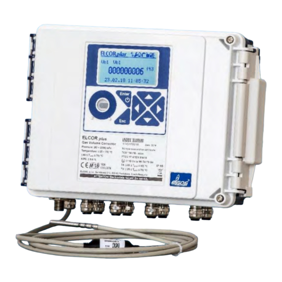
ELCOR, ELCORplus
GAS VOLUME CORRECTOR
ELCOR and ELCORplus
ELECTRONIC DATALOGGER
DATCOM and DATCOMplus
Device Description
Operating Instructions
Technical Description
Installation Instructions
Gas flow volume corrector at base conditions.
Approved for installation in potentially explosive atmospheres.
August 2020
Rev.4
Advertisement
Chapters
Table of Contents

Summary of Contents for Elgas ELCOR
- Page 1 ELCOR, ELCORplus GAS VOLUME CORRECTOR ELCOR and ELCORplus ELECTRONIC DATALOGGER DATCOM and DATCOMplus Device Description Operating Instructions Technical Description Installation Instructions Gas flow volume corrector at base conditions. Approved for installation in potentially explosive atmospheres. August 2020 Rev.4...
- Page 2 ELCOR, ELCORplus Safety Measures Only a person trained in accordance with the specification, safety regulations and CSN (EN) standards may operate the metering device. In addition, other legal and safety regulations for special cases of use in potentially explosive atmospheres must be taken into account. A similar measure applies to the use of the accessories.
-
Page 3: Table Of Contents
INTRODUCTION ......................9 1.1 Basic Description of the Device ................9 1.2 Securing the Device ..................... 11 1.3 Versions of the Device ..................12 1.3.1 ELCOR, DATCOM ....................12 1.3.2 ELCORplus, DATCOMplus ..................13 1.3.3 ELCORplus Indexer ....................14 SAFETY ........................15 2.1 General ....................... - Page 4 ELCOR, ELCORplus 5.1 Dimensions of the Device ..................42 5.1.1 ELCOR corrector ....................42 5.1.2 ELCORplus corrector ....................43 5.1.3 ELCORplus Indexer corrector ................. 44 5.2 Security Marks of the Device ................44 5.3 Data Plates ......................47 5.4 Mechanical Installation ..................49 5.4.1 Mounting the Device on the Plate ................
- Page 5 ELCOR, ELCORplus 6.9.2 Summary Status ....................103 6.9.3 Summary Status Reset ..................103 6.9.4 Device Test ......................104 6.9.5 Device Errors Display ................... 104 6.9.6 Status Word of the Device .................. 106 TECHNICAL DESCRIPTION OF THE DEVICE ..............108 7.1 Architecture of the Device ................. 108 7.2 Main parts of the device ..................
- Page 6 ELCOR, ELCORplus 8.4.1 Calculation of conversion number C for volume conversion ......141 8.4.2 Activities at Error Conditions Occurrence ............144 8.4.3 Respecting the Change of the Gas Flow Direction in the Gas Meter ....146 CONNECTING INPUTS ..................... 148 9.1 LF Pulse Inputs ....................
- Page 7 ELCOR, ELCORplus 12 ACCESSORIES ......................169 12.1 Plug-in Modules for ELCOR corrector ..............169 12.2 Plug-in Modules for ELCORplus corrector ............169 12.3 External Modules ....................170 12.3.1 Intrinsically Safe Sources for External Power Supply (ELCORplus only) ..... 170 12.3.2 Separation and Communication Modules ............170 12.4 Other Accessories ....................
- Page 8 ELCOR, ELCORplus PRODUCT FEATURES ....................194 5.1 Metrological characteristics and parameters ............. 194 5.2 Technical design and characteristics ..............194 TECHNICAL DESIGN ....................195 6.1 I/O board differences ..................195 6.2 External power supply ..................195 6.3 Plug-in modules - changes in use ............... 196 6.4 Sealing of the 2nd channel.................
-
Page 9: Symbols And Terms
… energy … substitute energy value EDTxx … digital transducer of pressure EDT 96 or of temperature EDT ELGAS ver. 2 … Communication protocol developed by ELGAS, s.r.o. electromagnetic compatibility and resistivity electromagnetic radiation Electronic gas volume corrector firmware, FW software in the device GOST 30319.2... - Page 10 ELCOR, ELCORplus absolute pressure at metering conditions absolute pressure at base conditions flow rate at measurement conditions (primary flow rate) flow rate at base conditions (converted flow rate) absolute temperature at measurement conditions (T = t + 273,15) gas temperature °C...
-
Page 11: Introduction
1 Introduction 1.1 Basic Description of the Device The ELCOR and ELCORplus gas volume correctors (hereinafter referred to as the device) are measuring devices designed to convert the volume of gas measured under operating conditions to the volume under base conditions. - Page 12 1 Introduction Trade Name of the Device These instructions specify the features and parameters of ELCOR and ELCORplus correctors. The device is also marketed as DATCOM and DATCOMplus electronic data logger. To some foreign markets, the device can also be supplied with a mechanical indexer under the name ELCORplus Indexer.
-
Page 13: Securing The Device
changing the device settings locally or remotely ELCOR, ELCORplus and ELCORplus indexer as an electronic volume corrector for billing purposes the same technical solution for DATCOM and DATCOMplus electronic data loggers for station monitoring and control ... -
Page 14: Versions Of The Device
1.3 Versions of the Device The gas volume corrector is manufactured and supplied in two types designated as ELCOR and ELCORplus, which differ in features, internal extension options and dimensions. The ELCOR and ELCORplus correctors are certified for commercial measurement according to 2014/32/EU. -
Page 15: Elcorplus, Datcomplus
1 Introduction - 2 x digital input - 2 x digital output (binary, pulse or analogue) - Optical head communication - 1 x RS232/RS485 communication interface - 1 x battery to power supply the corrector b) Optional extension: - 1 x internal modem module (including the battery to power supply the internal modem): - 2G modem (i.e. -
Page 16: Elcorplus Indexer
1 Introduction - PWR2 module to connect an external IS power supply to the modem, or - RS232 communication module for connecting an external modem - 1 x internal modem module (SLOT 5 position) /including battery for internal modem/: - 2G modem (i.e. GSM, dial-up CSD and GPRS connection); or - LTE modem The designations and features of the modules are specified in Section 3.11. -
Page 17: Safety
2 Safety 2 Safety Different versions of the devices in terms of safety The devices are supplied in terms of explosion safety in the following versions: intrinsically safe design - the whole device is intrinsically safe and is intended for Zone 0 or Zone 1 environments (see below) ... -
Page 18: General
2 Safety 2.1 General The device has been approved according to Directive 2014/34/EU (NV 116/2016 Coll.) and the following certificates has been issued for it: EU type-examination certificate (ATEX) for use in potentially FTZÚ 17 ATEX 0143X explosive atmospheres. IECEx FTZU 17.0023X IECEx Certificate of Conformity Important Notices: ATTENTION! - Page 19 2 Safety 1/ ELCOR (DATCOM) European Union marking (ATEX) Designation of Device and its internal equipment Environment explosion safety Basic design including module extensions: II 1G Ex ia IIB T4 Ga ZONE 0 - S0-NAM Interface for NAMUR gas meter encoder - S4-COM0 –...
- Page 20 2 Safety 3/ ELCORplus Indexer European Union marking (ATEX) Designation of Device and its internal equipment Environment explosion safety Basic design including module extensions: S0-MIE mechanical indexer interface S1-COM1 RS232/RS485 communication module II 1G Ex ia IIB T4 Ga ZONE 0 S1-2AI analog inputs module S1-2AO analog outputs module S3-PWR1 EVC external power supply...
-
Page 21: Special Conditions For Use
2 Safety 2.3 Special Conditions for Use ATTENTION! Under certain extreme circumstances, an electrostatic charge capable of explosion initiation can form on the plastic box. The device must not be installed in places where external conditions could result in electrostatic charge. -
Page 22: Technical Parameters
3 Technical Parameters 3 Technical Parameters 3.1 Mechanical Parameters ELCOR ELCORplus Mechanical dimensions (W x H x D) 210 x 190 x 93 mm 263 x 201 x 111mm More in paragraphs 5.1 Weight 1.5 kg 2.2 kg Cabinet material... -
Page 23: Safety, Explosion Protection
3 Technical Parameters 3.3 Safety, Explosion Protection ELCOR ELCORplus Explosion Safety Level - Basic version II 1G Ex ia IIB T4 Ga - With internal modem II 1G Ex ia IIB T3 Ga (battery-powered) - With internal modem powered from... -
Page 24: Device Accuracy
3 Technical Parameters - External power supply parameters ------------- See the technical parameters of the S3- PWR1 module Back-up Battery of the Corrector - Back-up battery yes (part of the CPU module) - Back-up battery life 16 years (ELCORplus indexer – 15 years) 5 3.5 Device Accuracy Relative error (in operational temperature range) - Max. -
Page 25: Pressure Measurement
345/2002 Coll. of the Ministry of Industry and Trade) - vary from country to country. In general, the validation period of a specified meter is determined by a country's decree. 3.6.2 Pressure Measurement ELCOR ELCORplus Number of pressure transducers, single channel Number of pressure transducers, dual... - Page 26 3 Technical Parameters 5 x UL for the range 80 520 kPa Mechanical resistance (without 2 times upper limit of the measurement range or leakage) 17MPa (whichever is lower) Measurement ranges - without MID certification (absolute pressure values) 80 1000 kPa 80 2000 kPa 80 3500 kPa 80 7000 kPa...
-
Page 27: Temperature Measurement
Mechanical resistance (without 2 x upper limit of the measurement range or leakage) 17 MPa ) (whichever is lower) 3.6.3 Temperature measurement ELCOR ELCORplus Number of temperature transducers, single channel Number of temperature transducers, ------------ dual channel Designation of the pressure... - Page 28 3 Technical Parameters device - Cable length for each input max. 30 m - LF pulse input Terminals DI1, DI3 Terminals DI1, DI4 (DI3 – for gas meters with (DI4 – for gas meters the option of detecting the with the option of rotation direction) detecting the rotation direction)
-
Page 29: Digital Outputs
- "ON" R < 100 k or U < 0.2 V - "OFF" R > 2 M or U > 2.5 V 3.8 Digital Outputs ELCOR ELCORplus - Number - Marking of the terminals (DOUT DO1, DO2 DO1, DO2, DO3, DO4... -
Page 30: Communication Inputs/Outputs
9600 Bd to 115200 Bd, adjustable - Communication protocol Selectable, depending on the firmware version (see Section 10) Communication interface RS485/RS232 (integrated on IO board) ELCOR ELCORplus - Number of integrated interfaces - Galvanic separation ---------- - Serial communication interface... -
Page 31: Optional Extension
3 Technical Parameters ELCOR ELCORplus Data archive - Archiving frequency t 1 hour as standard (adjustable from 1 s to 1 h) arch - Capacity approx. 112 000 records (i.e. approx. 12 years at =1 h), arch (changes dynamically depending on the configuration) -
Page 32: Communication Modules
3 Technical Parameters S0-SCR Interface module for ENCODER – SCR 1 6 F ELCOR ELCORplus - Max. number of modules in the device - Installation in the device SLOT 0 SLOT 0 - Number of inputs - Connection Two-wire - Type... - Page 33 RS232 terminals (GND, CTS, TxD, RxD) - Connection via IS separator B-RS module, or MTL5051 - Cable length 30 m max. M2G internal 2G modem ELCOR ELCORplus - Max. number of modules in the device - Device installation Separately SLOT 4...
-
Page 34: Modules For Connecting External Power Supply
- External power supply option - Type of module for external power S4-PWR2 supply connection 3.11.3 Modules for Connecting External Power Supply S3-PWR1 module of EVC power supply ELCOR ELCORplus Max. number of modules in the device - Installation in the device ------- SLOT3... -
Page 35: Analogue Inputs/Outputs Modules
PWR1+, PWR1- Cable length 30 m max. (min. conductor cross section 0.75 mm see paragraph 5.6.6) S4-PWR2 module of external power supply of the internal modem ELCOR ELCORplus Max. number of modules in the device - Installation in the device -------... -
Page 36: Other Modules
- Power supply voltage 5 V ÷ 28 V - Cable length for each output 30 m max. 3.11.5 Other Modules S0-EXT1 extension module ELCOR ELCORplus - Max. number of modules in the device - Installation in the device ----------... - Page 37 - Type of transducer EDT 96, EDT 101 - Max. cable length 100 m max. (total length of both transducers) S0-EXT1/HF extension module ELCOR ELCORplus - Max. number of modules in the device - Installation in the device ---------- SLOT 0...
- Page 38 3 Technical Parameters...
-
Page 39: Explosion Safety Parameters
Ii = 1 mA Pi = 1 mW Ci = 0, Li = 0 ELCOR - 3 inputs only: DI1, GND, DI2, GND, DI3, GND DOUT digital outputs: (terminals U0+, GND0, DO1, DO2, DO3, DO4) Ui = 15V Ii = 0.3A Pi = 0.5W... - Page 40 Ii = 0.15A Pi = 0.33W Ci = 4uF Li = 0 ELCOR includes the interface as a standard; not SLOT 1,2 TERMINALS. KP 100 110 - RS232 interface: (SLOT 1,2 TERMINALS: GND, CTS, RXD, TXD) Ui = 20V Ii = 0.15A...
- Page 41 4 Explosion Safety Parameters Ci = 1uF Li = 0 ELCOR includes the interface as a standard; these are not SLOT 1,2 TERMINALS. RS232 interface (KP 100 170): (TERMINALS COM0: GND, CTS, RXD, TXD) Ui = 20 V Ii = 150 mA ƩPi = 0,46 W...
- Page 42 4 Explosion Safety Parameters Ci = 0.46uF Li = 0 ELCORplus version only EXT1, EXT1/HF board (KP 100 130) – Digital Iputs: DI1, DI2 (NAMUR): (SLOT 0 TERMINALS: DI1-,DI1+,DI2-,DI2+) Uo = 10,0V Io = 11mA Po = 27mW 20uF 100uF Ui = 5,5 V Ii = 1 mA Pi = 1 mW...
- Page 43 4 Explosion Safety Parameters EXT1 board (KP 100 130) – Internal Bus IB1: (terminals EXT1-T: GND, U+, D+, D-) Same as Internal Bus IB0 and IB1. ELCORplus version only...
-
Page 44: Installation And Commissioning
At the bottom of the cabinet are metal cable glands for connecting the input and output signal cables with the possibility to connect the cable shielding conductively. 5.1 Dimensions of the Device 5.1.1 ELCOR corrector Fig. 1 ELCOR device dimensions... -
Page 45: Elcorplus Corrector
5 Installation and Commissioning 5.1.2 ELCORplus corrector Fig. 2 ELCORplus device dimensions... -
Page 46: Elcorplus Indexer Corrector
5 Installation and Commissioning 5.1.3 ELCORplus Indexer corrector Fig. 3 ELCORplus Indexer device dimensions 5.2 Security Marks of the Device Security marks on the device indicate the technical condition of the device from the point of view of unauthorized manipulation. Security Mark MID (Metrological Seal, not applicable to the logger) - Its form is prescribed by the certificate for Quality Management System for Production, Output Control and Testing according to Annex No 2, Procedure D, NV 120/2016 Coll., issued by Notified... -
Page 47: Fig. 4 Internal Security Marks Of Elcor
5 Installation and Commissioning User Mark - Inspection mark (seal) of the user according to the user’s needs. Fig. 4 Internal security marks of ELCOR... -
Page 48: Fig. 5 Internal Security Marks Of Elcorplus
5 Installation and Commissioning Fig. 5 Internal security marks of ELCORplus Fig. 6 External security marks of the device... -
Page 49: Data Plates
5 Installation and Commissioning 5.3 Data Plates Legend: Device designation Manufacturer’s address Pressure measurement range Warning to operators Temperature measurement Serial number of the device range Ambient temperature range Year of manufacture Max. permitted error of the IP rating device CE conformity mark EU Type examination certificate (metrological) -
Page 50: Fig. 7 Examples Of Data Plates
5 Installation and Commissioning Fig. 7 Examples of data plates... -
Page 51: Mechanical Installation
The mounting plate has been designed to be fitted with three-way valves supplied by ELGAS. The equipped mounting plate can be attached by means of screws and dowels to the wall, or by means of two clamps with locking devices on horizontal or vertical piping. -
Page 52: Mounting The Device On The Plate
5 Installation and Commissioning The device display and the visor for the optical head are protected from scratching by a transparent protective foil. Remove the protective foils after installation (they may impair the readability of the display and the functionality of the optical head). 5.4.1 Mounting the Device on the Plate Procedure: 1. -
Page 53: Fig. 9 Mounting Of The Elcor Convertor On The Mounting Plate
5 Installation and Commissioning Fig. 9 Mounting of the ELCOR convertor on the mounting plate 3. Attach a 6 mm connection pressure tube to the pressure sensor in the bottom of the cabinet to connect the 3-way valve. To attach the tube to the pressure sensor, use a cutting ring with M12x1.5 ERMETO nut. -
Page 54: Mounting The Device On A Pipe
5 Installation and Commissioning Fig. 10 Mounting dual channel ELCORplus on a mounting plate 5.4.2 Mounting the Device on a Pipe Clamps (see Fig. 11) with spacings corresponding to the pipe diameters are reeved through the openings in the mounting plate and inserted over the pipe. -
Page 55: Fig. 11 Mounting The Device On A Pipe (Elcorplus)
5 Installation and Commissioning Fig. 11 Mounting the device on a pipe (ELCORplus) For installation on piping or on ELGAS gas meters special holders shown on Fig. 12, Fig. 13 can also be used. -
Page 56: Installation Of Elcorplus Indexer On Gas Meter
5 Installation and Commissioning Fig. 12 Installation of ELCOR on piping using a special holder Fig. 13 Installation of ELCOR on ELGAS radial turbine gas meter 5.4.3 Installation of ELCORplus indexer on gas meter Place the gasket on the gas meter flange and then the ELCORplus indexer, which is supplied as a complete set including the attached mechanical indexer. -
Page 57: Fig. 14 Installation Of Elcorplus Indexer Device On The Gas Meter
5 Installation and Commissioning Fig. 14 Installation of ELCORplus indexer device on the gas meter Indexer gasket KP067 06 Sealing screw KP 067 07 5/16 x ¾ hexagon screw ST.5 Zn M8 washer DIN125-ISO7089 Zn Make sure the indexer counter rotates in the right direction. If not, loosen the bolts remove the cover at the back of the indexer (see Fig. -
Page 58: Connecting The Pressure Transducer
5 Installation and Commissioning After the indexer adjustment is finished it is imperative to carry out a RESET of the device! You can reset the device either from the keypad of the device - menu System data (see section 6.8.2), or via the service software [42], [43]. Changing the indexer settings will not be accepted without resetting the device. -
Page 59: Fig. 16 Mounting The Temperature Sensor On The Pipe
5 Installation and Commissioning The weld-on fitting must be welded in such a way that the thermowell is in the vertical position, or inclined under 45° angle from the vertical axis with the cavity up (Fig. 16). Into the weld-on fitting, a thermowell of the appropriate length for the used pipe diameter is screwed over a copper gasket (see Table 2). -
Page 60: Electric Installation
Devices manufactured by ELGAS are designed to have very high immunity to interference. They are tested according to valid standards (set of standards ČSN EN 61000 4) for radiation (EMI) and resistance (EMC) to electromagnetic interference in an industrial environment (see [29], [30], [31]). - Page 61 5 Installation and Commissioning The first level is protection against the effects of lightning. The protection is realized by overvoltage protection SPD type 1, which is placed in the low-voltage part of the substation or in the main switchboard of the building. It serves mainly to limit atmospheric overvoltage. The second level of protection is usually realized by overvoltage protection SPD type 2, which is usually located in the secondary switchboard and further reduces the magnitude of the overvoltage value for the next third stage.
-
Page 62: Fig. 18 Interconnection Pipelines
(Fig. 18). Fig. 18 interconnection pipelines 5.5.2.3 Device grounding The device (corrector ELCOR, ELCORplus, ELCORplus corrector for zone 2 and the DATCOM, DATCOMplus, DATCOMplus recorder for Zone 2) does not have to be grounded from a functional point of view. - Page 63 5 Installation and Commissioning In the case of devices with an external pressure sensor, the cable shield on the sensor side is conductively connected to the sensor housing (provided by the manufacturer) - see paragraph 5.6.1 In this case, the device is galvanically connected to the piping (grounded) via the cable shield of the external pressure sensor.
- Page 64 5 Installation and Commissioning standards ČSN EN 50 174. It is generally recommended: Store power cables (230/400 V) separately from signal cables (24 V, analog/digital signals) preferably at a distance of 20 cm or more or use closed metal cable trays with a shielding partition.
-
Page 65: Fig. 19 Installation Of A Converter With Pressure And Temperature Transducer, External Power Supply And Remote Communication With An Emphasis On Emc
5 Installation and Commissioning Fig. 19 Installation of a converter with pressure and temperature transducer, external power supply and remote communication with an emphasis on EMC... -
Page 66: Electrical Connection
5 Installation and Commissioning 5.6 Electrical Connection The text below describes electrical connection of the corrector with other devices. For the described connections to work properly, the device should also be set correctly up. The device can be set up either using the service software [42], [43] or from the device keypad (see Section 6.7). - Page 67 5 Installation and Commissioning The device is equipped with metal cable glands size PG7 and PG9. These glands are designed for cables of the following diameters: 3.0 ÷ 6.5 mm 4.0 ÷ 8.0 mm The cable glands are arranged as shown in Fig. 21. The minimum cross section is specified for the recommended shielded cables listed below.
-
Page 68: Fig. 21 Cable Glands Arrangement
5 Installation and Commissioning ELCORplus ELCOR ELCORplus indexer Fig. 21 Cable glands arrangement Cable Size Cable Size Pressure (1st channel) Temperature (2nd channel) Temperature (1st channel) Communication Gas meter (1st channel) External pressure (2nd channel) HF gas meter, encoder Digital output (DOUT), communication... -
Page 69: Connecting Gas Meters
- Pulse output of the gas meter for detecting the rotation direction ) DI2 terminal of the ELCOR corrector can also be configured to connect the LF pulse output of another meter. However, it cannot be used as a metrological quantity. -
Page 70: Table 4 Cables Recommended To Connect The Gas Meter
(e.g. PS-E, PS-E/A). Gas Meter with NAMUR or SCR Encoder ELCOR, ELCORplus – The module of the interface of the encoder must be fitted in the SLOT 0 position. The gas meter is connected to terminals 1 and 2. The external power supply of the corrector is not necessary. -
Page 71: Fig. 22 Connecting Lf Gas Meter To Elcor
5 Installation and Commissioning 5.6.2.1 LF Gas Meter, Single Channel corrector Fig. 22 Connecting LF gas meter to ELCOR Fig. 23 Connecting LF gas meter to ELCORplus (single channel) -
Page 72: Fig. 24 Connecting Lf Gas Meter With The Detection Of Rotation Direction To Elcor
5 Installation and Commissioning 5.6.2.2 LF Gas Meter with the Detection of Rotation Direction Fig. 24 Connecting LF gas meter with the detection of rotation direction to ELCOR Fig. 25 Connecting LF gas meter with the detection of rotation direction to ELCORplus... -
Page 73: Fig. 26 Connecting Lf Gas Meters To Elcorplus (Dual Channel)
5 Installation and Commissioning 5.6.2.3 LF Gas Meter, Dual Channel Fig. 26 Connecting LF gas meters to ELCORplus (dual channel) Fig. 27 Connecting LF gas meters to ELCORplus (dual channel, gas meter with the detection of rotation direction) -
Page 74: Fig. 28 Connecting Hf Gas Meters To Elcorplus (Dual Channel)
5 Installation and Commissioning 5.6.2.4 HF Gas Meter Fig. 28 Connecting HF gas meters to ELCORplus (dual channel) 5.6.2.5 Gas Meter with Encoder Fig. 29 Connecting gas meter with NAMUR encoder to ELCORplus... -
Page 75: Connecting Binary Inputs
Fig. 30 Connecting gas meter with SCR encoder to ELCORplus 5.6.3 Connecting Binary Inputs ELCOR - Terminal DI2 is the standard for binary input connection. If the DI3 terminal or DI1 has not been used to connect the gas meter, these terminals also can be used. -
Page 76: Connecting Binary Outputs
5 Installation and Commissioning 5.6.4 Connecting Binary Outputs ELCOR – with 2 digital outputs available, DO1 and DO2 terminals on the DOUT terminal block. ELCORplus – with 4 digital outputs available, DO1 to DO4 terminals on the DOUT terminal block. -
Page 77: Connection Of Pressure And Temperature Transducers
5 Installation and Commissioning Fig. 32 Connecting digital outputs via B-DO separation barrier (ELCORplus) 5.6.5 Connection of pressure and temperature transducers These transducers are connected to the I / O board in the IB0 terminal block, respectively terminal block IB1 (ELCORplus only). Furthermore, they can be connected to the IB1 terminal block of the EXT1-T terminal board of the EXT1 module. -
Page 78: Connecting External Power Supply
5 Installation and Commissioning Fig. 33 EDT 96 and EDT 101 transducers connection The EDT 96 pressure transmitter and the EDT 101 temperature transmitter are supplied by the manufacturer calibrated in whole measurement range. The calibration and correction data are stored in the transducer´s internal memory when the transmitter is calibrated and the resulting measured data already included with the corrections is passed to the instrument control unit. -
Page 79: Fig. 34 Connecting The External Power Supply Of The Corrector
5 Installation and Commissioning Unitronic LiYCY 2 x 1.0 13 m 6.3 mm Lappkabel External power supply of 4-wire Unitronic LiYCY 4 x 1,0 13 m 7.3 mm the convertor and the shielded Lappkabel modem Table 8 Cables recommended for external power supply for the corrector and the modem 5.6.6.1 External Power Supply for the Corrector (Measurement Part) External power supply can be used with ELCORplus or ELCORplus Indexer. -
Page 80: Fig. 35 Ps-M External Power Supply For The Internal Modem From Ps-M Source
5 Installation and Commissioning the PS-M external intrinsically safe source. The S4-PWR2 module must be installed in SLOT 4. Power from an external intrinsically safe PS-M source is fed to the PWR2 terminals. In the event of a power failure, the modem battery (HB-03, HB-04, etc.) performs the power backup function. -
Page 81: Connection Of Rs232/Rs485 Communication
Fig. 36 External power supply to the corrector and the internal modem 5.6.7 Connection of RS232/RS485 Communication ELCOR - one RS232/RS485 communication interface is built in the device. For communication, either RS232 or RS485 is used. The cable is connected to the RS232/RS485 terminal block. If there is no internal modem in the device, the communication can be extended by another independent RS232 communication interface using the S4-COM0 module. -
Page 82: Table 10 Recommended Cables For Rs232 And Rs485 Of The Corrector
5 Installation and Commissioning Communication Cable Recommended type of Max. Cable Cable Ø interface gland cable lenght RS232 4-wire Unitronic LiYCY 4 x 0,34 30 m 5,7 mm shielded Lappkabel RS485 4-wire Unitronic LiYCY 4 x 0,34 100 m *) 5,7 mm shielded Lappkabel... -
Page 83: Fig. 37 Communication Via Rs232/Rs485 Using B-Rs Module
5 Installation and Commissioning Fig. 37 Communication via RS232/RS485 using B-RS module... -
Page 84: Fig. 38 Connecting B-Rs When External Modem Is Connected
5 Installation and Commissioning Fig. 38 Connecting B-RS when external modem is connected Fig. 39 ELCORplus, communication via two independent interfaces RS232/RS485... -
Page 85: Commissioning
5 Installation and Commissioning Fig. 40 Communication using the barrier MTL 5051 5.7 Commissioning The device is delivered either in the operating state with the battery connected or in the off mode with the battery disconnected. Both the battery of the device (B-03 etc.) and the modem battery (HB-03, HB-04, etc.) are equipped with a cable with a connector by which they are connected to the device. -
Page 86: Connecting The Battery
5 Installation and Commissioning WARNING! All the connectors in the device contain a mechanical safety lock against accidental disconnection. To disconnect the connector, first press the lock to release the connector, then pull the connector gently out of the socket. Never apply force grasping and pulling the cable, it can be damaged. -
Page 87: Connecting The Modem Battery
The version of the device with internal GSM/GPRS modem can be delivered with a disconnected modem battery. 5.7.2.1 ELCOR When commissioning the device, the battery outlet (HB-03, HB-04, etc.) with the connector must be plugged into the modem module connector. -
Page 88: Fig. 43 Connecting The Modem Battery For Elcor
Modem module Connector of the modem battery Fig. 43 Connecting the modem battery for ELCOR 5.7.2.2 ELCORplus, ELCORplus Indexer When commissioning, the modem power supply battery pack (HB-03, HB-04, etc.) with the connector must be plugged into the connector of the module that is installed in the SLOT 4 position. -
Page 89: Installing Sim Card In The Modem
5 Installation and Commissioning Note: For longer time storing, it is recommended to remove the batteries from the device or, if necessary, at least disconnect them by pulling out the battery connector. 5.7.3 Installing SIM Card in the Modem 5.6.3 Install the SIM card into the modem The device is delivered without the modem SIM card. -
Page 90: Operating The Device
6 Operating the Device 6 Operating the Device The device is not equipped with a power switch. The device turns automatically into the operation mode when the battery is inserted in the device. The device registers the LF pulses even with the main battery removed. -
Page 91: Keypad
6 Operating the Device 6.1 Keypad Pressing the Enter key for 2 seconds turns the display on Moving from one menu item into lower level menu (submenu) When displaying actual values, Enter will scroll through the screen to display all the quantities one after another ... - Page 92 6 Operating the Device Pos. Meaning Symbol Description The compressibility is being calculated or the firmware is verified after the remote download update Device status The device works flawlessly (sum status) An error has occurred in the device The device has generated a warning message The external power supply of the device is connected Battery charge status 100 %...
-
Page 93: Fig. 46 Basic Navigation From The Home Screen
6 Operating the Device Battery charge status 42 ÷ 58 % Battery charge status 25 ÷ 42 % Battery charge status 8 ÷ 25 % Battery charge status 0 ÷ 8 % Communication via internal modem or via optical Communication head status Communication via the modem or the head disabled... -
Page 94: Main Menu
6 Operating the Device 6.3 Main Menu The selected menu item is highlighted inversely on the display. Fig. 47 Main menu of the device and the first-level submenu... -
Page 95: Actual Values Menu
6 Operating the Device 6.4 Actual Values Menu By pressing the key the actual values are displayed. To scroll through the displayed data, use the arrow up and down keys Scrolling through the displayed values The asterisk flag indicating exceeding the measuring range of the analogue quantity Fig. -
Page 96: Fig. 50 Display Of The Settings Archive
6 Operating the Device changed. To end archive viewing, press the key Moving forward in time Moving backward in time (to the history) Moving to the next information at the selected time Moving to the previous information at the selected time ID of the user that made the setting Settings made at the selected time (4.12.2018, 13:45:37) Fig. -
Page 97: Device Parameters Menu
6 Operating the Device 6.6 Device Parameters Menu The following parameters are displayed in the Communication menu: General parameters (network address1, network address2) IR head (baud rate, communication protocol) Internal modem (baud rate, communication protocol, communication device) ... -
Page 98: Fig. 52 Example Of The Displayed Information On Device Components
6 Operating the Device In the Modules menu, you can view the basic data of the modules, transducers, batteries, and other system components. Use the keys to scroll through the data. Module identification number Module designation Serial number of the module Number of the slot in which the module is installed or the identification of the internal communication bus to which the module (transducer) is connected... -
Page 99: Device Configuration Menu
6 Operating the Device 6.7 Device Configuration Menu In this menu, the device parameters can be set directly from the device keypad. Setting device parameters from the keypad can be protected: By the service switch (the switch must be set to ON) ... -
Page 100: System Data Menu
6 Operating the Device To edit a parameter, press the keys to move the parameter to the first row on the display (the parameter is displayed inversely). Start the editing by pressing the Enter key. The edited position in the row is indicated with the symbol . -
Page 101: Communication
6 Operating the Device 6.8.3 Communication This option makes it possible to: View important information about the modems connected to the device (the modem must be set in the device parameters), Verify that the modem settings are correct by simple testing the ... -
Page 102: Table 12 Rssi Signal Strength Conversion Table Between Dbm, %, And Relative Units
6 Operating the Device Information about signal strength at the location of the device. The Modem Status command does not measure the signal strength. If this information appears on the display, it is the data ascertained at the time when the modem last logged on to the network. -
Page 103: Table 13 Error Codes Of The Modem
6 Operating the Device modem returns "ERROR" SIM card errors PIN code requested, but not stored in the configuration data PIN code requested, incorrect PIN code stored in the configuration data PIN blocked, PUK code requested SIM card is not inserted GSM network registration errors registration in the GSM network takes longer than usual (>... -
Page 104: Frozen Values
6 Operating the Device 6.8.3.3 Power on Modem This option will turn the modem on for 5 minutes (i.e. 300 seconds; the remaining time in seconds to turning off the modem shows in the top right corner of the display). This command is useful, for example, to test the communication when setting up the device (basically simulates the function of the internal parameter "Timer - Service Window"... -
Page 105: Diagnostics
If there are any problems with the operation of the device for any reason, technical support personnel may be contacted. Contacts are available at http://www.elgas.cz/kontakty. To help you find a solution to the problem, we recommend providing as much as possible information about your device and connections to related devices nearby. -
Page 106: Device Test
6 Operating the Device switch must be ON. If switched to OFF, a message is displayed that the initialization cannot be performed. 6.9.4 Device Test After selecting this menu item, the device tests its internal state and displays a list of detected errors and warnings. -
Page 107: Table 14 List Of Events - Error Messages (Err Indication)
6 Operating the Device - not used - E13 battery disconnected Battery is disconnected E14 P1 under limit Pressure range exceeded (1st channel) E15 P1 above limit E16 P1 error Pressure transducer error E17 T1 under limit Temperature range exceeded (1st channel) E18 T1 T1 above limit E19 T1 error Temperature transducer error... -
Page 108: Status Word Of The Device
6 Operating the Device W14 Q1 Q1 max. limit channel) W15 Qb1 Qb1 min. limit Flow rate at base conditions user limits exceeded (1 channel) W16 Qb1 Qb1 max. limit - not used - - not used - W19 P2 P2 min. limit Pressure user limits exceeded (2nd channel) W20 P2 P2 max. - Page 109 6 Operating the Device interval. Assignment of a specific status word bit to each monitored event is shown in Table 14 Table 15. When viewing the status in the device archives by the utility SW [42], [43] the status word is already displayed in decoded readable form.
-
Page 110: Technical Description Of The Device
7 Technical Description of the Device 7 Technical Description of the Device WARNING! All the connectors in the device contain a mechanical safety lock against accidental disconnection. To disconnect the connector, first press the lock to release the connector, then pull the connector gently out of the socket. Never apply force grasping and pulling the cable, it can be damaged. -
Page 111: Main Parts Of The Device
ELCORplus Indexer is identical with ELCORplus. ELCOR has only SLOT 0 available to extend its features. The basic design can be extended by a modem module installed to the right in the device enclosure outside of the I/O board. -
Page 112: Fig. 55 Main Parts Of The Elcorplus Device
SLOT 0 (placed terminal cover meter under modem battery in connection ELCORplus) cable adapter for external modem I/O board antenna connection module installed in SLOT 1 Internal modem (ELCOR) -
Page 113: Elcorplus Indexer - Description Of Mechanical Indexer
Table 16 Connection of mechanical indexer to SLOT 0 terminals The electrical connection of the mechanical indexer to the SLOT 0 terminals is secured with a seal. (Elgas security marks). -
Page 114: Fig. 56 Mechanical Indexer - Settings Of Tamper Parameters In The Corrector Via Compass Software (Signal Of An Attempt To Disturb The Function Of The Indexer By An External Magnetic Field)
7 Technical Description of the Device Fig. 56 Mechanical indexer – settings of TAMPER parameters in the Corrector via Compass software (signal of an attempt to disturb the function of the indexer by an external magnetic field) -
Page 115: Fig. 57 Functional Diagram Of Elcor
7 Technical Description of the Device Fig. 57 Functional diagram of ELCOR... -
Page 116: Fig. 58 Functional Diagram Of Elcorplus
7 Technical Description of the Device Fig. 58 Functional diagram of ELCORplus... -
Page 117: Modules, Principles Of Use
The supplied expansion modules are designed for installation into the slots located on the I/O board. ELCOR device is equipped with SLOT 0 only, ELCORplus and ELCORplus Indexer with SLOT 0 to SLOT 5. For each module, the manufacturer determines into which slot it can be fitted. -
Page 118: Marking Of Modules
7 Technical Description of the Device ATTENTION! The device and modules are equipped with CMOS components that are sensitive to static charges. Do not touch the outlets of the components and connectors. When working, do not use synthetic fabrics (including clothing) from which a static electricity spark could arc to the circuit. -
Page 119: Table 17 Labeling Of Internal Modules
S0-MIE Indexer Module Interface for mechanical SLOT 0 indexer ELGAS (only ELCORplus indexer) S0-SCR SCR Module Interface for SCR encoder of gas meter S0-NAM NAMUR Module Interface for NAMUR encoder of gas meter... -
Page 120: Installing The Modules
7 Technical Description of the Device 7.4.2 Installing the Modules The device design allows additional extension or alteration of the input/output modules (SLOT 1, SLOT 2) and external power supply of the whole device (SLOT 3) and the communication module (SLOT 4). ATTENTION! If the device classification from the point of view of explosion safety has been changed after retrofitting of certain modules (see paragraph 2), the... -
Page 121: Replacement Of The Internal Modem
7 Technical Description of the Device The battery-powered modem is located in SLOT 4. To connect an external power supply source, you need to move the modem to SLOT 5 and place the external power module in SLOT 4. ... -
Page 122: Fig. 61 Modem Replacement
7 Technical Description of the Device Fig. 61 Modem replacement... -
Page 123: Power Supply Of The Device
7 Technical Description of the Device 7.5 Power Supply of the Device ATTENTION! ! The danger of explosion if the battery is incorrectly replaced for a different type ! Only batteries prescribed by the manufacturer (see paragraphs 3.4 and 3.11.2), approved by the laboratory for this device and complying with the parameters for explosive environment may be used in the device. -
Page 124: Batteries To Power The Device
): -25 °C to +70 °C or -40 °C to +70 °C ambient temperature ): -30 °C to +65 °C Under these conditions, the lifetime of the batteries supplied for typical ELCOR and ELCORplus configurations is shown below: 7.5.1.1 ELCOR/ELCORplus Volume Corrector Basic Variant a) Basic configuration... - Page 125 - SLOT2: not fitted - SLOT3: S3-PWR1 - SLOT4: S4-PWR2 or modem - SLOT5: Modem or not fitted 7.5.1.2 ELCOR/ELCORplus volume corrector variant with connected NAMUR or SCR+ encoder a) Encoder reading period 1 hour With the display OFF Display ON all the time...
- Page 126 Elster, RMG and FMG. 2) The encoder reading period is limited, see section 9.4. ELCOR HW Configuration: - IB0: 1x EDT 96, 1x EDT 101 (metrological transducers) - SLOT0: S0-NAM or S0-SCR module with encoder connected...
-
Page 127: Replacing The Battery
- SLOT3: S3-PWR1 - SLOT4: S4-PWR2 or modem - SLOT5: Modem or Not Mounted 7.5.1.5 ELCOR/ELCORplus other variants Contact the manufacturer to determine the battery life of a different HW/SW configuration of the device that is not stated here (see section 6.9). - Page 128 7 Technical Description of the Device The device indicates discharged battery by E9 error message in the device diagnostics (see Section 6.9.5). All data in the device, archives and parameter settings are stored in non- volatile (energetically independent) memory and will remain intact even if the device is disconnected from the power supply, including the disconnection of the backup battery.
-
Page 129: Battery To Power The Modem
7 Technical Description of the Device Fig. 62 Main battery 7.5.3 Battery to Power the Modem Discharged battery of the modem is indicated by the E27 error message in the device diagnostics; low voltage of the modem battery is indicated by the W30 warning message. -
Page 130: Replacing The Modem Battery
7.5.6 External Power Supply External power supply can be used for ELCORplus and ELCORplus Indexer. For ELCOR, external power supply cannot be used. The external power supply to the device does not provide power to the internal modem. For an internal modem, separate external power supply must be used. -
Page 131: Digital Outputs, Modified Use
The wiring diagram for the external supply of the modem is specified in Section 5.6.6.2. 7.6 Digital Outputs, Modified Use ELCOR has 2 digital outputs DO1 and DO2 in basic design, ELCORplus and ELCORplus Indexer have 4 digital outputs DO1 to DO4. These outputs run to the DOUT terminal block of the input/output board (I/O board). -
Page 132: Fig. 63 Placing Jp1 Jumper On I/O Board
7 Technical Description of the Device 3.6V. An example of use is, for example, the connection of DO1 (DO2) to the digital input of another converter (miniELCOR, maxiDATCOM, etc.), which meets this condition. Notice If jumper JP1 is fitted and terminal DO1 (DO2) is connected to a device that provides a DC voltage greater than 3.6 V on the wire connected to terminal DO1 (DO2), the device will be damaged! Attention: this mode reduces the operating ranges of the DO1 and DO2 outputs... -
Page 133: Internal Modem, Using External Antenna
7 Technical Description of the Device 7.7 Internal Modem, Using External Antenna The internal M2G, M4G modem is powered by a stand-alone HB-03/HB-03D battery. The modem is fully controlled by the device parameters. Due to the current consumption of the modem, it is necessary to choose the mode and timing of the transmitted data and to control the switching ON and OFF of the modem with respect to the modem battery. -
Page 134: Software
7 Technical Description of the Device Unscrew the connector nut (3) and insert it into the holder in the cover (4). Remove the blind cap (5) at the bottom of the enclosure. Install the HF cable reducer. Insert the panel connector of the HF cable reducer with the rubber O-ring into the blind cap opening (5) and fasten it outside the enclosure using a nut and a washer. -
Page 135: Downloading Application Firmware Using "Remote Download" Method
"App" part or the "App" part together with the "Metrolog" can be downloaded. The digital signature contained in the application firmware file (* .srec) confirms that standard testing has been performed at ELGAS, s.r.o. and that the "Metrolog" module complies with the valid certificate of the relevant notified body. -
Page 136: Substitute Volume Values
7 Technical Description of the Device The compressibility factor of the gas expresses the variation of the natural gas properties from the properties of the ideal gas. By setting the parameters, a specific method according to a specific standard (AGA NX-19 mod, AGA8-G1, AGA8-G2, SGERG-88, AGA8-92DETAIL, GOST 13390.2, or GOST 13390.3) can be selected for compressibility factor calculation. -
Page 137: Conversion Of Volume To Energy
7 Technical Description of the Device where: Corrected volume at the measurement conditions (volume corrected based on the correction profile of the gas meter) Volume at the measurement conditions (primary volume) Flow rate at the measurement conditions (primary flow rate) The linear interpolation method is used as the implicit interpolation method to determine the values between the calibration points. - Page 138 7 Technical Description of the Device WARNING: When changing the unit, the absolute value of the counter E (Es) is not recalculated. The addition volume is then read observing the new measurement unit. If the instrument performs energy calculations (Hs is activated in the device parameters), the reference conditions must be consistent, i.e.: - pb, tb to convert the volume V to volume Vb - p2, t2 for combustion heat to calculate E...
-
Page 139: Fig. 65 Volume And Energy Calculations - Calculation Scheme
7 Technical Description of the Device Fig. 65 Volume and energy calculations - calculation scheme... -
Page 140: Metrological Features
8 Metrological Features 8 Metrological Features 8.1 Temperature Measurement To measure temperature, the device uses the EDT 101 digital transmitter with the PT1000 temperature sensor. Mechanically, the transducer consists of a sensor in a 5.7 mm stainless steel shank with a length of 50 mm from which the cable is routed. -
Page 141: Table 20 Limitation Of Standard Applicability Given By Limitation In Compressibility Calculation (Aga, Sgerg)
8 Metrological Features using one of the following methods implemented in the device: AGA NX-19-mod, SGERG-88, AGA8-G1, AGA8-G2, GOST 13390.2, GOST 13390.3 or AGA8-DETAIL. Other quantities also enter into the calculation, especially the reference values of pressure Pb and temperature Tb and the current values of pressure p and temperature t of the gas. -
Page 142: T Conversion
8 Metrological Features Method Pressure Measurement Range GOST 13390.2 GOST 13390.3 100 ÷ 520 kPa -23,15 ÷ +70 °C -23,15 ÷ +70 °C 100 ÷ 1000 kPa -23,15 ÷ +70 °C -23,15 ÷ +70 °C 100 ÷ 2000 kPa -23,15 ÷ +70 °C -23,15 ÷... -
Page 143: Volumes Measurement And Calculation
8 Metrological Features instead of "calculated" to "Constant value". The range of the constant entered is not limited. Fig. 68 Setting the constant compressibility value for calculating C (SW Compass) 8.4 Volumes Measurement and Calculation To measure and calculate volumes, the following counters are used for each channel in the device: Volume counter under the measurement conditions (primary volume) Corrected volume under the measurement conditions (volume corrected... -
Page 144: Fig. 69 Setting The Replacement Pressure Value (Compass Sw)
8 Metrological Features 8.4.1.1 Gas pressure - measured or fixed value By default, the measured value of the gas pressure p in the pipeline by the pressure sensor is used to calculate C. In some special cases, instead of the measured pressure value, the value entered into the device as a constant when configuring the device can be used for the calculation. -
Page 145: Fig. 70 Constant Pressure Value Setting (Sw Compass)
8 Metrological Features Fig. 70 Constant pressure value setting (SW Compass) The size of the substitute value can be changed by the user after turning the service switch to the ON position. Switching measured value p / constant value is protected by a metrological switch. 8.4.1.2 Gas temperature - measured or fixed value By default, the measured value of the gas temperature t in the pipeline by the temperature sensor is used to calculate C. -
Page 146: Activities At Error Conditions Occurrence
8 Metrological Features "Spare const.value". The set value should be as close as possible to the real value of the gas temperature in the pipeline. Fig. 71 Setting the replacement temperature value (SW Compass) Fig. 72 Setting a constant temperature value (SW Compass) The size of the substitute value can be changed by the user after turning the service switch to the ON position. - Page 147 8 Metrological Features volume counter at the basic conditions (V ) and start to be calculated from substitute pressure or temperature values and stored in the substitute volume counter at basic conditions (V ). Under this condition, the values are not stored in the volume counter at the basic conditions (V The device error condition occurs in these cases: 1.
-
Page 148: Respecting The Change Of The Gas Flow Direction In The Gas Meter
8 Metrological Features - Primary volume counter at error conditions (substitute primary volume) - Volume counter at base conditions (corrected volume) - Base volume counter at error conditions (substitute corrected volume) Fig. 73 Storing volumes in the counters in error-free and error-free condition If the substitute compressibility is used in the calculation because of accuracy deviation outside the value permitted under the selected calculation standard, while neither p and t are outside the measuring range, the converted volume is stored in the spare counter. -
Page 149: Fig. 74 Processing The Volumes At The Gas Meter Revers Rotation
8 Metrological Features Fig. 74 Processing the volumes at the gas meter revers rotation Note: If the instrument is set to respect the change of gas flow direction through the gas meter, it is possible to switch on the counter in the instrument parameters, in which the amount of gas flow is stored during the gas meter return. -
Page 150: Connecting Inputs
9 Connecting Inputs 9 Connecting Inputs Three digital inputs can be connected to the ELCOR device, marked as DI1 to DI3. The ELCORplus has 4 digital inputs in the basic version, marked DI1 to DI4. Other inputs can be added to the device via plug-in modules. -
Page 151: Fig. 75 Ext1-T Add-On Terminal Board For S0-Ext1 Module
9 Connecting Inputs NOTICE! If the S0-EXT1 module is installed in the device, while no HF input of this module is used and the device is powered only by the battery (no external power supply is used), it is necessary to deactivate the HF inputs of this module (service SW [42], [43]). -
Page 152: Lf Pulse Inputs
9 Connecting Inputs Input Module Terminals Mounting options 4-20 mA analogue S1-2AI SLOT 1 SLOT 2 Table 26 Options of analogue inputs for the ELCORplus Indexer device 9.1 LF Pulse Inputs There are used to count pulses from the gas meter. For these inputs, flow measurement function can be selected. -
Page 153: Device Specifics When Using The Encoders
9 Connecting Inputs The corrector is connected with the encoder by a shielded two-wire cable. The electrical connection of the encoders with the device is described in Section 5.6.2.5. When making the connection, the signal polarity must be respected. The encoder data is transmitted to the corrector in the measurement frequency. Setting a short measurement frequency shortens the battery life. -
Page 154: Communication With The Device
10 Communication with the Device 10 Communication with the Device In order to communicate with other instruments, the device is equipped with several communication devices: ELCOR ELCORplus ELCORplus Indexer DATCOM DATCOMplus Optical interface for IR head RS232/RS485 integrated ----- -----... - Page 155 The utility SW [43], [42] uses this protocol only; to switch to another data link layer, the ELGAS version 2 protocol is just nested in another data link layer (the tunnel). Only the ELGAS version 2 and CTR protocols can be used to download the firmware (protected by a metrological seal).
-
Page 156: 62056-21 (Iec-1107) Optical Interface
Network address2. If more than one device is connected to the communication line, the addresses must be set so that no collision occurs. The ELGAS communication protocol uses both parts of the address, the MODBUS communication protocol uses only Address1. -
Page 157: Connecting Communication Devices Via Rs232 Interface
For example, a PC is a DTE device, a modem is a DCE device. Generally (RS232): In case of ELCOR, ELCORplus is connected via external module B-RS, B-RS/A. This communication module includes an internal signal crossing. Therefore, connecting to a PC and modem will look like this:... -
Page 158: Connecting An External Modem
An external modem with RS232 communication interface can be connected to the device. For the ELCOR, the external modem is connected either to the terminals of the RS232 communication interface on the I/O board or to the S4-COM0 module. In this case, the S4-COM0 module is installed in the device in a position where the M2G or M4G internal modem is normally fitted. - Page 159 10 Communication with the Device packet.
-
Page 160: Function Description
11 Function Description 11 Function Description The device offers highly variable and user-configurable options for displaying of values and storing the quantities. The user can decide which quantities to display as actual values and which quantities should be stored in the archives. 11.1 Quantities Designation The quantities are designated using the symbols shown in the table “Symbols and Terms”... -
Page 161: Archives
11 Function Description 11.3 Archives The values in the archives are ordered in time slots. Each time slot includes the time data of the slot and the values of the quantities selected for archiving. The measured and computed quantity values can be stored in the following archives: ... -
Page 162: Monthly Archive
11 Function Description Gas compressibility factor - mean value Minimum/maximum conversion, gas compressibility factor Binary quantities Binary input - state Binary output - state Setpoints - state Device and transducer communication errors - state Binary internal Other quantities Counter/ timer - absolute Device status Notes: 1) The day or hour is stored together with the value (or in combination, where suitable) -
Page 163: Binary Archive
11 Function Description 11.3.4 Binary Archive The archive stores the states of binary inputs together with status bits calculated and stored in the system, and the errors of each device. The values can only be stored in this archive if the status of any stored binary is changed. -
Page 164: Other Features Of The Device
Saturday or Sunday (holiday). Each schedule has its own identification number and the time of activation can be set separately for each schedule. 11.6 Protection against change of Metrological Parameters ) This data is valid for the OEM ELGAS s.r.o. device version. -
Page 165: Protection Switches
11 Function Description The device is protected against unauthorized manipulation (especially with data that affect the metrological characteristics of the device) with a metrological and service switch and uses password system security. Changes to the device settings and other operations are stored in the settings archive. -
Page 166: Table 32 Password Format
11.6.2.1 Password Groups (Valid for ELGAS version 2, MODBUS, and CTR) The passwords are divided into 5 groups. Users of the "Administrators" group have the highest rights, the users of the "User 3" group have the lowest rights. Higher-level users have lower-level users rights, plus some others. - Page 167 11 Function Description Setting Tb and Pb Changing the device status Changing a restriction Setting Vb, Vbs Setting the schedule of the tariff currently active When the metrology switch is set to ON, it is possible to: ...
-
Page 168: Levels Of Access
11 Function Description User 1 821 to 830 Depending on the service switch, the parameters are divided into groups. For the effect of the service switch, see Table 31. Parameters influencing metrological properties: Setting the substitute values to calculate the conversion factor ... - Page 169 11 Function Description User Level - Common user of the device. At this level, reading all the data from the device and setting a large number of parameters is allowed. It is not possible to change the parameters directly affecting the metrological properties of the device. For more details, see Table 34.
-
Page 170: Table 34 User Access Level - For The "Full" Function Of The Service Switch
11 Function Description Assigning the influence of the service switch on parameter writing Setting the V and Vs counters Changing the method of calculating the compressibility factor Setting the gas composition Setting units and constants ... -
Page 171: Accessories
12 Accessories 12 Accessories 12.1 Plug-in Modules for ELCOR corrector Module Designation Slot S0-SCR Interface for SCR gas meter encoder SLOT 0 S0-NAM Interface for NAMUR gas meter encoder Internal modem 2G M4G, LTE-Cat1E Internal modem LTE cat.1-E M4G, LTE-Cat1US Internal modem LTE cat.1-US... -
Page 172: External Modules
12 Accessories M4G, LTE-Cat1E Internal modem LTE cat.1-E M4G, LTE-Cat1US Internal modem LTE cat.1-US M4G, LTE-CatM1 Internal modem LTE cat.M1-US Extension Internal Module BARP Module for barometric pressure measurement (ELCORplus only) (must be specified in the order, cannot be installed by user) 12.3 External Modules The main function of these modules is to ensure external power supply of the device and external power supply of internal modems and to ensure correct connection of other cooperating devices,... -
Page 173: Fig. 77 Elcorplus, Example Of Use Of External Modules
12 Accessories B-RS Separation barrier for RS485 B-RS/A B-DI Separation barrier for digital inputs (2 pcs) B-DO Separation barrier for digital outputs (4 pcs) B-DO/A B-IB Separation barrier for internal bus Fig. 77 ELCORplus, example of use of external modules... -
Page 174: Fig. 78 Elcorplus, Example Of Use Of External Modules
12 Accessories Fig. 78 ELCORplus, example of use of external modules... -
Page 175: Fig. 79 Elcor, Example Of Use Of External Modules
12 Accessories Fig. 79 ELCOR, example of use of external modules Fig. 80 ELCOR, example of use of external modules... -
Page 176: Other Accessories
12 Accessories 12.4 Other Accessories 4-20 mA analogue output module HIE-04 B IR head with USB communication interface (max.115 200 Bd) HIE-04 IR head with USB communication interface (max. 38 400 Bd) (production ceased) HIE-03 IR head with RS232 communication interface (max. 38400 Bd) (production ceased) EDT 101 Temperature transducer... -
Page 177: Appendix 1: Device Variant With The Segment Display
Appendix 1: Device variant with the segment display Appendix 1: Device variant with the segment display 1 Device operation For viewing data, the device is equipped with a two-line segment LCD display with icons. Using this display brings these changes in the display features when compared with a standard graphic display: ... -
Page 178: Display Of The Device
Appendix 1: Device variant with the segment display In order to simplify the operation by a non-trained user, the option to display actual values one after another by pressing the RIGHT key is included. Before this, it is necessary to exit by pressing the Esc key several times to the top menu level (Vb). -
Page 179: System Menu
Appendix 1: Device variant with the segment display Indication of the status of the metrological and service switch lighted: - The metrology or service switch is ON Indication of the status checksum not shown: - status OK lighted: - Warning or Error The communication channel of the device is switched to the optical interface. - Page 180 COMMUN communication address COM.GEN. general ADR1 communication address 1 ADR2 communication address 2 IR.HEAD optical head SPEED baud rate PROT. communication protocol ELCOR: internal modem COM0 ELCORplus: communication device connected via SLOT 4,5 SPEED baud rate PROT. communication protocol...
- Page 181 Appendix 1: Device variant with the segment display COM.DEV. communication device ELCOR: interface RS232/RS485 COM1 ELCORplus: communication device connected via SLOT1 SPEED baud rate PROT. communication protocol COM.DEV. communication device ELCORplus: communication device COM2 connected via SLOT2 SPEED baud rate PROT.
- Page 182 Appendix 1: Device variant with the segment display S.N.GAS gas meter serial number pressure measurement P.RANGE pressure range S.N. P serial number of the transducer temperature measurement T.RANGE temperature range S.N. T serial number of the transducer setting the device parameters from the CONFIG keyboard SERV...
- Page 183 Appendix 1: Device variant with the segment display primary volume setting converted volume setting substitute primary volume setting substitute converted volume setting energy setting substitute energy setting S.N.GAS gas meter serial number setting QMAX maximum gas meter flow rate setting CLEAR.A deleting archives contents DATA.AR.
- Page 184 Appendix 1: Device variant with the segment display After the signal strength is successfully measured, the value in percent (SIG: xx Table 12 [%], converted to dBm - see ) is displayed. Automatic shutdown after 2 min or by shutdown by the user. Turning the modem power supply on manually from the keypad switches on, or switches on and...
-
Page 185: Actual Menu - Actual Values Display
Appendix 1: Device variant with the segment display 2.1.1 ACTUAL Menu – Actual Values Display (serial number 2 of the main menu) Immediate values of metrological quantities and the set non-metrological quantities are displayed (the non-metrological quantities are set in the parameters of the instrument using the utility program [42]). -
Page 186: Diag Menu Item - The Device Diagnostics
Appendix 1: Device variant with the segment display LATCH – Freezing the Actual Values The actual values measured are frozen at the display on pressing the key. The frozen values of the quantities (Vb, Vm, P, T etc.) can be displayed in the standard way when displaying the actual values. -
Page 187: Appendix 2: Elcorplus Version For Zone 2
Appendix 2: ELCORplus version for Zone 2 Appendix 2: ELCORplus version for Zone 2 1 Introduction This appendix describes a version of the ELCORplus that has a different type of explosion protection than the one described in the previous section of the manual and is intended for use in a hazardous area Zone 2. -
Page 188: Safety
Appendix 2: ELCORplus version for Zone 2 2 Safety 2.1 General The device ELCORplus for Zone 2 is approved according to Directive 2014/34/EU (NV No. 116/2016 Coll.) and has been released with the following certificate: Certificate of examination certificate (ATEX) for use in FTZÚ... -
Page 189: Special Conditions Of Use
Appendix 2: ELCORplus version for Zone 2 ELCORplus (DATCOMplus) Explosion proof Device and internal equipment Environment II 3G Zone 2 basic design, including module extensions: Ex ic nA IIB T4 Gc S0-NAM Interface for NAMUR gas meter encoder S0-SCR Interface for SCR gas meter encoder S0-EXT1 Expansion module S0-EXT1/HF Expansion module S1N-COM1 RS232/RS485 communication module... -
Page 190: Risks Of Use
Appendix 2: ELCORplus version for Zone 2 2.4 Risks of Use The housing is made of polycarbonate. On the top lid is placed foil keyboard made of polyester. In some extreme cases, electrostatic charges may build up on the cabinet surface. Its energy could cause the initial explosive atmosphere to initialize. -
Page 191: Safety Parameters Of Signals On Terminals
Appendix 2: ELCORplus version for Zone 2 3 Safety parameters of signals on terminals 3.1 Intrinsically safe terminals Digital inputs DIN: (terminals DI1, GND, DI2, GND, DI3, GND, DI4, GND) Uo = 6,5 V Io = 2 mA Po = 3 mW 20 F 100 F 10 mH... - Page 192 Appendix 2: ELCORplus version for Zone 2 Po = 27 mW 20 uF 100 uF 1 mH 1 mH Ui = 5,5 V Ii = 1 mA Pi = 1 mW Ci = 0, Li = 0 Module EXT1, EXT1/HF (KP 100 130) – Digital Inputs DI1, DI2 (NAMUR): (terminals SLOT0 TERMINALS: DI1-, DI1+ ,DI2-, DI2+) Uo = 10,0 V Io = 11 mA...
-
Page 193: Terminals With Protections „Na
Appendix 2: ELCORplus version for Zone 2 Module EXT1 (KP 100 130) – analog inputs AIN: (terminals EXT1-T: GND, AI1, GND, AI) Ui = 28 V Ii = 93 mA Pi = 0,66 W Ci = 40 nF Li = 0 Module EXT1 (KP 100 130) - Internal Bus IB1: (terminals EXT1-T: GND, U+, D+, D-) Same parameters as Internal Bus IB0 and IB1 only for ELCORplus... -
Page 194: Device Identification Of Elcorplus For Zone 2
Appendix 2: ELCORplus version for Zone 2 4 Device identification of ELCORplus for Zone 2 There are two labels on the front of the device: a production label (corrector or recorder), and an additional label with a warning about opening the device in a potentially explosive ... -
Page 195: Production Label For Recorder
Appendix 2: ELCORplus version for Zone 2 4.2 Production label for recorder 4.3 Additional label Both labels are situated on the front part of device. -
Page 196: Product Features
Appendix 2: ELCORplus version for Zone 2 5 Product features 5.1 Metrological characteristics and parameters Metrological characteristics and parameters of device ELCORplus for Zone 2 are identical to the standard version of the intrinsically safe ELCORplus device. 5.2 Technical design and characteristics Technical design and characteristics of the device ELCORplus for zone 2 are almost no different from intrinsically safe but a modified version of the I/O board and the associated changes in plug- in modules are used. -
Page 197: Technical Design
Appendix 2: ELCORplus version for Zone 2 6 Technical design 6.1 I/O board differences I/O board (position 12 in Fig. 55 of manual), The board contains terminal blocks for connecting external devices and slot connectors for plug-in modules, in the version for Zone 2 the following differences: does not contain SLOT 3 (S3-PWR1 cannot be used). -
Page 198: Plug-In Modules - Changes In Use
S0-MIE Indexer Module Interface for mechanical SLOT 0 indexer ELGAS (only for ELCORplus indexer for Zone 2) S0-SCR SCR Module Interface for SCR encoder of gas meters S0-NAM NAMUR Module Interface for NAMUR encoder... -
Page 199: Table 37 Plug-In Modules, Elcorplus For Zone 2
Appendix 2: ELCORplus version for Zone 2 M4G, LTE-CatM1U Modem LTE-Cat M1 Mod U Internal modem LTE, cat. M1- BARP Barometric Sensor Module for barometric pressure (only ELCORplus) *) These modules are functionally identical to intrinsically safe modules but they have terminals for connection of external devices protected by the type of protection "nA". -
Page 200: Sealing Of The 2Nd Channel
Appendix 2: ELCORplus version for Zone 2 6.4 Sealing of the 2nd channel Fig. 81 Sealing of the 2nd channel on ELCORplus for zone 2... -
Page 201: Technical Parameters - Modules For External Power Supply
Appendix 2: ELCORplus version for Zone 2 7 Technical parameters – modules for external power supply S4N-PWR3 Module of external power supply EVC and internal modem ELCORplus for Zone 2 max. count of modules in device installation in EVC device SLOT 4 module identification providing external power to the converter (EVC) - Page 202 Appendix 2: ELCORplus version for Zone 2 S4N-PWR4/12V Module of external power supply EVC and internal modem ELCORplus for Zone 2 max. count of modules in device installation in EVC device SLOT 4 module identification providing external power to the converter (EVC) circuits and internal modem from the 12Vdc power supply network galvanic separation...
-
Page 203: Connection Of Inputs And Outputs
Appendix 2: ELCORplus version for Zone 2 8 Connection of inputs and outputs Connecting the equipment to the intrinsically safe terminals is described in the main section of the manual and also applies to the ELCORplus for Zone 2. A different connection method applies to terminals that are not intrinsically safe but have "nA" type protection applied, i.e. -
Page 204: Identification Of Cable Glands
Appendix 2: ELCORplus version for Zone 2 Fig. 82 Terminals with protection „nA“ 8.2 Identification of cable glands The cable glands for intrinsically safe cables are marked with a blue gland nut cover on the device ELCORplus for zone 2. For cables with standard signals (i.e. -
Page 205: External Power Connection
Appendix 2: ELCORplus version for Zone 2 Fig. 83 The deployment of the cable gland Type of signal des. cable gland pressure (1. channel) intrinsically safe temperature (1. channel) intrinsically safe gas meter (1. channel) intrinsically safe gas meter HF, encoder intrinsically safe gas meter (2. - Page 206 Appendix 2: ELCORplus version for Zone 2 appropriate electrical qualification. During all activities with electrical equipment, switch off the power supply and check that the device is not live. Keep the inside of the device free of moisture to prevent possible short circuits.
-
Page 207: Fig. 84 Connecting Of External Power Supply
Appendix 2: ELCORplus version for Zone 2 des. Part pug-in module S4N-PWR3 (S4N-PWR4) connector-plug with terminals for external power supply connector-plug for external power supply to board of module external power supply cover of external power supply Fig. 84 connecting of external power supply Note: Do not connect the external power supply to the terminals when the connector plug is inserted... -
Page 208: Connection Of Communication Devices Via Rs232 / Rs485 Interface
Appendix 2: ELCORplus version for Zone 2 Notice If the converter is powered by an external power supply, it is necessary for the conversion battery power supply (B-03) of the converter to be inserted and connected in the device. 8.4 Connection of communication devices via RS232 / RS485 interface For communication, ELCORplus for Zone 2 must have at least one S1N-COM1 communication module. -
Page 209: Table 40 Recommended Cables For Rs232 And Rs485 Converters
Appendix 2: ELCORplus version for Zone 2 Lappkabel from SLOT 1 (or SLOT 2) and Unitronic LiYCY 10 x 0,25 DOUT (4x) Lappkabel from SLOT 1, SLOT 2 and DOUT Unitronic LiYCY 14 x 0,14 (4x) Lappkabel Table 40 Recommended cables for RS232 and RS485 converters Recommendation: When you connect an external modem to the device, we recommend using the RS232 communication interface to ensure full duplex communication. -
Page 210: Examples - Block Diagram Of Connection
Appendix 2: ELCORplus version for Zone 2 9 Examples - block diagram of connection Fig. 85 Block diagram, ELCORplus for Zone 2 with ext. 12V power supply... -
Page 211: Fig. 86 Block Diagram, Elcorplus For Zone 2 With Ext. 230V Power Supply
Appendix 2: ELCORplus version for Zone 2 Fig. 86 Block diagram, ELCORplus for zone 2 with ext. 230V power supply... -
Page 212: Appendix 3: Compass - Data Export
Appendix 3: Compass – Data Export Appendix 3: Compass – Data Export 1. Export parameters to PDF At the end of the generating process is opened this window:... - Page 213 Appendix 3: Compass – Data Export Preview of generated document:...
- Page 214 Appendix 3: Compass – Data Export 2. Read the archive from the device Click on the export button after reading any archive from the device. Use the arrows to select which columns you want to export. The resulting PDF file contains the export of parameters (as in paragraph 1) and plus the last 30 records from the selected archive.
- Page 215 Appendix 3: Compass – Data Export 3. Export to 4. Export to TXT (DOC)
- Page 216 Appendix 3: Compass – Data Export...
- Page 217 Appendix 3: Compass – Data Export 5. Export of graph...
-
Page 218: References
References 13 References Act no. 22/1997 Sb. Zákon o technických požadavcích na výrobky a o změně a doplnění některých zákonů (Act no. 22/1997 Coll. on the Technical Requirements for Products, and on a change and addition to certain laws ČSN EN 60079-0 ed.4 (33 2320): III.2013–Elektrická zařízení pro výbušnou plynnou atmosféru–Část 0: Všeobecné... - Page 219 Modicon Modbus Protocol Reference Guide, Modicon Inc., Industrial Automation Systems, 1996 [20] FTZÚ 17 ATEX 0143X – EU-Type Examination Certificate, Gas-Volume Conversion Device ELCOR, ELCORplus, ELCORplus indexer, Datalogger DATCOM, DATCOMplus, FTZÚ Ostrava-Radvanice [21] FTZÚ 19 ATEX 0002X – Type Examination Certificate, Gas-Volume Conversion Device type ELCORplus for Zone 2, Datalogger type DATCOMplus for Zone 2, FTZÚ...
- Page 220 References [35] EN 50174-2:2018 Information technology – Cabling installation – Part 2: Installation planning and practices inside buildings [36] EN 50174-3:2013 Information technology – Cabling installation – Part 3: Installation planning and practices outside buildings [37] LR1502 Certificate of Compliance, QPS Evaluation Services Inc., September 2019...
-
Page 221: Related Documents
COMPASS – Software description. User Manual. Elgas, s.r.o. [39] EDT 96 Pressure transducer. User Manual. Elgas, s.r.o. [40] EDT 101 Temperature transducer. User Manual. Elgas, s.r.o. [41] Accessories for ELCOR and ELCORplus correctors and DATCOM and DATCOMplus data loggers, ELGAS, s.r.o. -
Page 222: Software
Software 15 Software [42] COMPASS.exe, Elgas, s. r. o., supplied with the device [43] TELVES.exe, Elgas, s. r. o., supplied with the device [44] Reliance, GEOVAP Pardubice... -
Page 223: Trade Marks Used
Trade Marks Used 16 Trade Marks Used IrDA ® - trade mark of Infrared Data Association company ModBus ® - trade mark of Modicon company... -
Page 224: List Of Figures
Fig. 23 Connecting LF gas meter to ELCORplus (single channel) ..........69 Fig. 24 Connecting LF gas meter with the detection of rotation direction to ELCOR ....70 Fig. 25 Connecting LF gas meter with the detection of rotation direction to ELCORplus ..... 70 Fig. - Page 225 Fig. 41 Connecting the device battery ..................85 Fig. 42 ELCORplus indexer with alkaline battery B-03A located above slot 0 ......85 Fig. 43 Connecting the modem battery for ELCOR ..............86 Fig. 44 Connecting the modem battery for ELCORplus ............... 86 Fig.
- Page 226 Fig. 77 ELCORplus, example of use of external modules ............171 Fig. 78 ELCORplus, example of use of external modules ............172 Fig. 79 ELCOR, example of use of external modules ..............173 Fig. 80 ELCOR, example of use of external modules ..............173 Fig.
-
Page 227: List Of Tables
Table 21 Limitation of ranges applicability given by limitation in compressibility calculation (GOST) ............................140 Table 22 Options of digital inputs for the ELCOR device ............148 Table 23 Options of digital inputs for the ELCORplus device ............ 148 Table 24 Options of analogue inputs for the ELCORplus device ..........149 Table 25 Options of digital inputs for the ELCORplus Indexer device........ - Page 228 Table 39 Terminal block assignment of SLOT 1 and SLOT 2 when fitted with S1N-COM1 module ............................206 Table 40 Recommended cables for RS232 and RS485 converters ........... 207 GAS VOLUME CONVERTORS ELCOR and ELCORplus ELECTRONIC DATA LOGGERS DATCOM and DATCOMplus Prepared by:...
Need help?
Do you have a question about the ELCOR and is the answer not in the manual?
Questions and answers