Sign In
Upload
Manuals
Brands
Electronaut Manuals
Recording Equipment
M97
User Manuals: Electronaut M97 Vari-Mu Compressor
Manuals and User Guides for Electronaut M97 Vari-Mu Compressor. We have
1
Electronaut M97 Vari-Mu Compressor manual available for free PDF download: User Manual
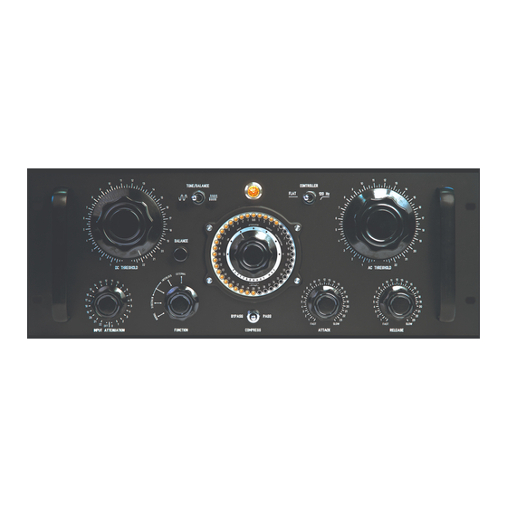
Electronaut M97 User Manual (39 pages)
Brand:
Electronaut
| Category:
Recording Equipment
| Size: 10 MB
Table of Contents
Seriously.
3
Table of Contents
3
Contact Information
5
DECLARATION of CONFORMITY
5
Thank You Sincerely
6
Getting Started
8
Inspection
8
Opening the Crate
8
Removing the M97 from the Crate
8
Figure 1 - the Little Plastic Vile in the Center of the Shockwatch™ Label will
8
Figure 2 - Pry up the Tabs on the Wooden Crate and Lift off the Top Cover
8
Figure 3 - the M97 Is Insulated from Shock and Suspended in Place by Two
8
Thorough Inspection Procedure
9
Configuration
9
Front Panel
9
Rear Panel
9
Figure 4 - the METER MODE Switch in the off Position
9
Figure 5 - the FUNCTION Switch Should be Set to NORMAL Mode
9
Figure 6 - the LINE VOLTAGE Switch MUST be Configured to the Correct Setting
9
B+ Adjust (325V) Knob
10
Balance/Chassis Knob
10
Iec Power Inlet Switch
10
Figure 7 - the B+ ADJUST Control Permits Adjustment of the High Voltage
10
Figure 8 - the BALANCE/CHASSIS Control Is a Secondary Balancing Control Used to Fine-Tune the Balance the Push-Pull Audio Amplifier
10
Figure 9 - the IEC Power Inlet, with the Switch Shown in the on Position
10
Installation
11
Airflow and Thermal Considerations
11
Calibration
11
POWER up the M97
11
Calibrating the B+ Voltage
11
Figure 10 - the METER MODE Switch in the on Position
11
Calibrating the Balance
12
The Balancing System
12
Balance Calibration Procedure
12
Figure 11 - the METER MODE Switch in the B+ Position
12
Figure 12 - the B+ ADJUST Control Permits Adjustment of the High Voltage
12
Figure 13 - the AC THRESHOLD Control Should be Set to the Maximum Counter-Clockwise Position During the BALANCE Procedure
13
Figure 14 - the TONE/BALANCE Switch Shown in BALANCE Mode
13
Figure 15 - Set the METER MODE Switch to the ATTENUATOR Position, then Adjust the Input Attenuator until a Level of 0 Db Is Displayed
13
Figure 16 - Switch the METER MODE Switch to the OUTPUT Position to See the
13
Figure 17 - the Front Panel BALANCE Knob Is Used to Adjust the Symmetry of the Audio Amplifier in Order to Minimize Distortion
13
Balance/Chassis
14
At this Point the M97
14
Should be Properly Calibrated and Ready for Service
14
Figure 18 - the BALANCE/CHASSIS Control Is a Secondary Balancing Control Used to Fine-Tune the Balance the Push-Pull Audio Amplifier
14
Reference
15
Input Attenuator
15
Figure 19 - the INPUT ATTENUATOR Is a 3-Pole 23-Position Balanced Bridged-T
15
Figure 20 - the High Frequency Response Can be Extended by Setting the
16
THE INPUT ATTENUATOR and the HIGH FREQUENCY RESPONSE
17
The Controlling Amplifier
18
DC Threshold
18
Attack
18
Figure 21 - the DC THRESHOLD Control Raises the Threshold as It Is
18
Figure 22 - the AC THRESHOLD Control Increases the Limiter Action as It
18
Figure 23 - the ATTACK Control Slows down the Limiter's Response Time as
18
Release
19
ATTACK and RELEASE INTERDEPENDENCE
19
The Usability of the Fastest Attack Times
19
Electronaut Company
19
Suggested Set-Up for Transient Limiting
19
Figure 24 - the RELEASE Control Slows down the Limiter's Recovery Time as It
19
Understanding the Effects of the Ac and DC Threshold Controls
20
Compression Curves
21
Electronaut Company
21
Figure 26 - the Three Graphs Show Level Sweeps Across the Range of the AC THRESHOLD Control at Fixed DC THRESHOLD Positions
21
A Note about Workflow
22
The Metering System
23
Meter Mode Knob
23
The Signal Generator
24
Making Good Use of the Tone and Meter
24
The Compression Curve Is
24
Figure 28 - Switching the TONE/BALANCE Toggle to the Left Mutes the Output and Turns on the Test Tone
24
High Pass Filter
25
Bypass/Compress/Pass
25
Bypass
25
Compress
25
Pass
25
Figure 29 - the CONTROLLER Switch Provides a Flat Frequency Response and a High-Pass Filter Option at the Input of the Controlling Amplifier
25
Figure 30 - It Is Possible to Either Completely Bypass the Audio Circuitry (BYPASS), Process the Audio Without Gain Reduction (PASS), and Table 1 -Part Numbers for Replacement IEC Power Cables
25
The FUNCTION SWITCH
26
Normal
26
Sidechain
26
Interlock
26
M97 Compressor/Limiter
26
Sidechain/Interlock
26
External
26
Linking Two M97S for Stereo
27
Block Diagram of Signal and Control Circuitry
28
Figure 32 - a Simplified Block Diagram of the M97'S Signal Path and Controlling
28
Power Scheme
29
Meter Mode Switch
29
Iec Power Inlet
29
Iec Power Cable
29
Figure 33 - the IEC Cable Provided with the M97 Has a Locking Mechanism that Works in Tandem with the IEC Power Inlet
29
Replacing the Fuses
30
Main Fuses
30
Internal Fuses
30
Figure 34 - the Main Fuses Are Contained Inside a Removable Cartridge. that
30
Figure 35 - Removing the Fuse Cartridge with a Small Flat Screwdriver
30
Replacement Fuse Part Numbers
31
Tube Complement
31
Table 3 - the M97 Ships with a Standard and Recommended Tube Complement
31
Figure 36 - the Main Printed Circuit Board, Showing the Location of the Internal Fuses and the Tube Positions
32
Optional Remote-Cutoff Tubes
33
Tube Socket Wiring and Tube Compatibility
34
Heater Voltage Toggle Switch
34
Replacing the Tubes
34
Table 4 - a Partial List of Compatible Tube Types
34
Figure 39 - Tube Bases that Are Compatible with the M97
34
Warranty & Registration
35
Servicing
35
Specifications
36
User's Guide 36
36
Acknowledgements
37
Rein Narma
37
Dr. Daniel Flickinger
37
Early Believers
37
User's Guide 38 Table of Figures
38
Table of Figures
38
Advertisement
Advertisement
Related Products
Electronaut M63
Electronaut Categories
Recording Equipment
Amplifier
More Electronaut Manuals
Login
Sign In
OR
Sign in with Facebook
Sign in with Google
Upload manual
Upload from disk
Upload from URL